
Robot cleaner having RF antenna

a robot cleaner and antenna technology, applied in carpet cleaners, process and machine control, instruments, etc., can solve problems such as unfavorable communication between the two, and achieve the effect of improving the performance of wireless communication of the robot cleaner

Inactive Publication Date: 2009-02-10
LG ELECTRONICS INC
View PDF12 Cites 28 Cited by
  • Summary
  • Abstract
  • Description
  • Claims
  • Application Information

AI Technical Summary

Benefits of technology

[0007]Therefore, an object of the present invention is to provide a robot cleaner having an RF antenna capable of improving performance of wireless communication of a robot cleaner.
[0009]By installing the RF antenna at the robot cleaner, a limitation of a distance and an angle between a transmission sensor and a reception sensor can be reduced, and although there is an obstacle between the main body of the robot cleaner and the remote controller, the main body of the robot cleaner and the remote controller can smoothly communicate with each other.
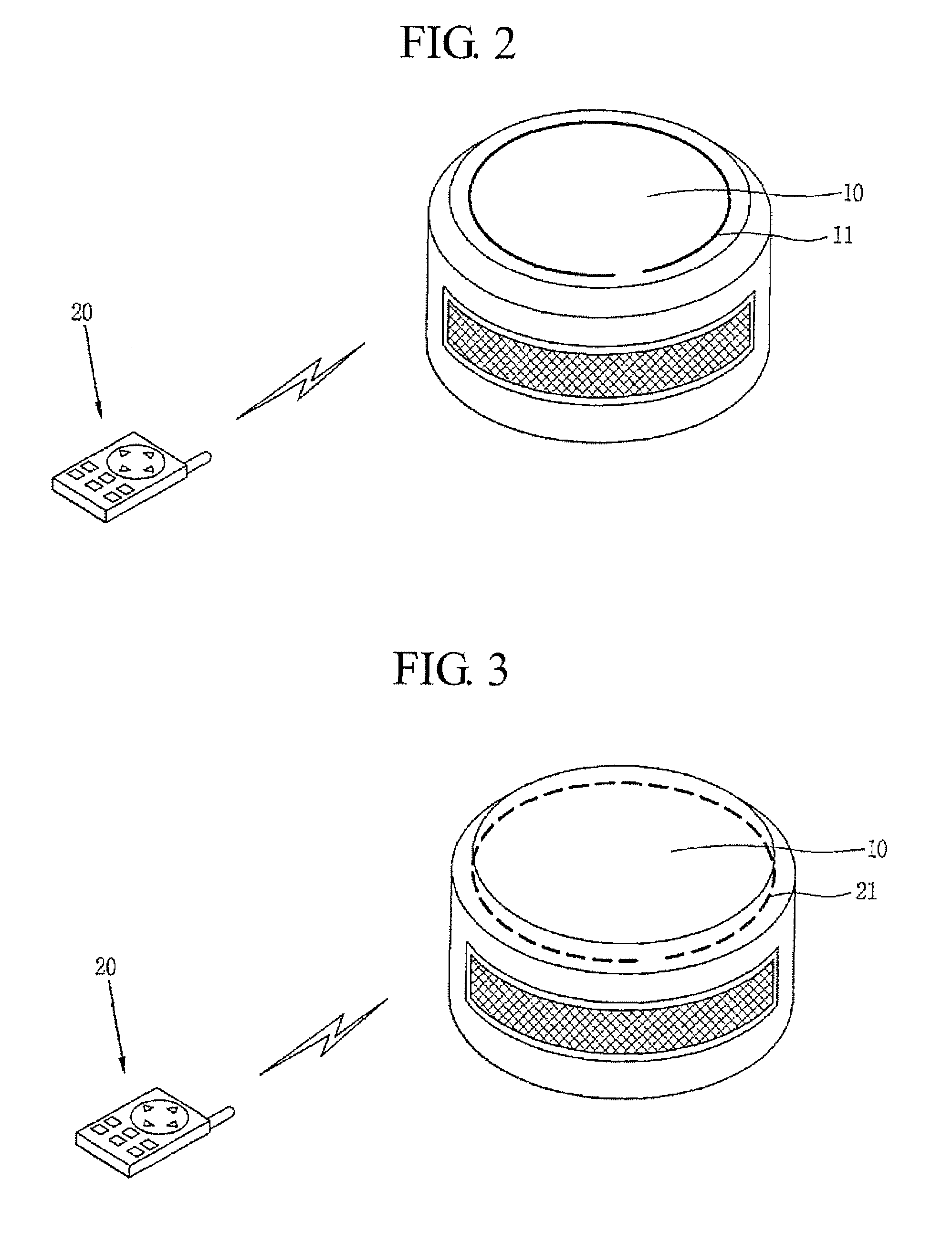
[0013]When the RF antenna is installed to be exposed outside the main body, the robot cleaner may interfere with its traveling due to an obstacle positioned in a cleaning area, so by installing the RF antenna within the main body, the traveling performance and cleaning efficiency of the robot cleaner can be improved.
[0016]Preferably, the RF antenna is disposed to be tightly attached on an inner surface of the main body of the robot cleaner in order to prevent an interference with other components within the main body.
[0019]By forming the RE antenna with the plurality of loop structures that are electrically connected or in the spiral structure, the length of the antenna can increase to perform communication with the remote controller more smoothly.

Problems solved by technology

However, a robot cleaner having the wireless communication module adopting the IrDA method has a problem that a distance and an angle between a transmission sensor and a reception sensor are limited, and when there is an obstacle between the main body of the robot cleaner and remote controller, communication is not smoothly made therebetween.

Method used


Image

  • Robot cleaner having RF antenna
  • Robot cleaner having RF antenna
  • Robot cleaner having RF antenna

Examples


Embodiment Construction

[0025]The present invention will be described with reference to the accompanying drawings. A detailed description for a known art or construction will be omitted to have the gist of the present invention clarified.

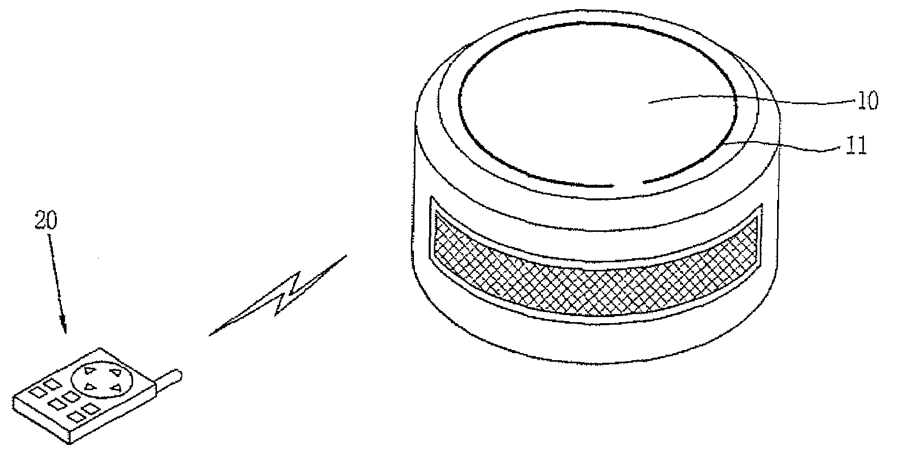
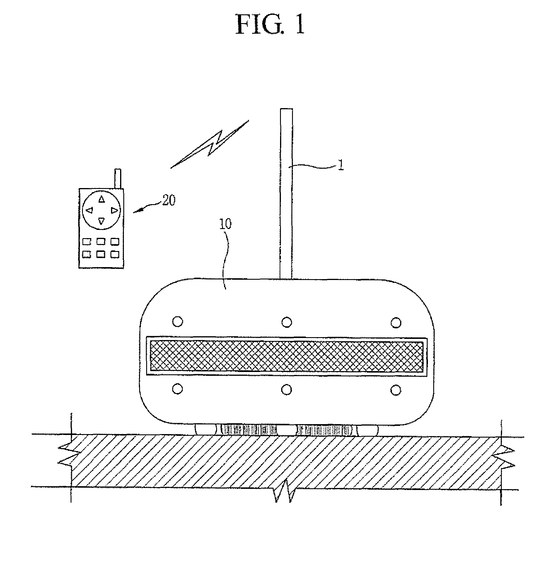
[0026]FIGS. 1 and 2 show the structure of a robot cleaner having an RF antenna according to one embodiment of the present invention.

[0027]As shown in FIGS. 1 and 2, the robot cleaner having an RF antenna according to one embodiment of the present invention includes a main body 10 and RF antennas 1 and 11 that have a length appropriate for communication with a remote controller 20 and installed to be exposed on an outside of the main body 10 of the robot cleaner.

[0028]The main body 10 of the robot cleaner includes a dust container (not shown) for keeping sucked dust, a sensor for sensing a cleaning area and an obstacle and a driving unit (not shown) for traveling.

[0029]As shown in FIG. 1, the RF antenna 1 is formed to be protruded vertically on an upper surface of the main ...


PUM


Abstract

A robot cleaner including: a main body; and an RF antenna installed at the main body with such a length appropriate for communication with a remote controller. Because the RF antenna is installed within the main body, the degradation of traveling performance and cleaning efficiency caused as the antenna contacts with an external obstacle can be prevented.

Description

BACKGROUND OF THE INVENTION[0001]1. Field of the Invention[0002]The present invention relates to a robot cleaner having an RF antenna and, more particularly, to a robot cleaner having an RF antenna capable of improving performance of wireless communication of a robot cleaner and obtaining traveling (movement) capability.[0003]2. Description of the Related Art[0004]In general, a robot cleaner is a device for automatically cleaning an area desired to be cleaned by sucking debris such as dust in the cleaning area while traveling there under the control of a controller according to signals of a remote controller.[0005]A main body of the robot cleaner includes a wireless communication module so as to be connected for inter-communication with the remote controller, and as the wireless communication module, a wireless communication module that is not expensive and uses an IrDA method is commonly used.[0006]However, a robot cleaner having the wireless communication module adopting the IrDA ...

Claims


Application Information

Patent Timeline
Patent Type & Authority Patents(United States)
IPC IPC(8): H01Q1/24H01Q1/36H01Q11/12
CPCA47L9/2805A47L9/2852A47L9/2894A47L11/4011H01Q1/27H01Q1/44A47L2201/00G05D1/0016G05D2201/0203G05D1/0033A47L9/28A47L9/00
Inventor SUNG, JI-HOONROH, HEE-SUK
Owner LG ELECTRONICS INC
Learn More