Antenna structure for wireless communication device

a wireless communication and antenna technology, applied in the direction of resonant antennas, anti-theft devices, lock applications, etc., can solve the problems of human body affecting the transmission of radio waves, and lowering the intensity of transmitted radio waves, so as to improve the wireless communication capability

Inactive Publication Date: 2011-09-20
KK TOKAI RIKA DENKI SEISAKUSHO
View PDF16 Cites 10 Cited by
  • Summary
  • Abstract
  • Description
  • Claims
  • Application Information

AI Technical Summary

Benefits of technology

[0006]It is an object of the present invention to provide an antenna structure for a wireless communication device that improves the wireless communication capability.

Problems solved by technology

The human body may block radio waves when the portable device is performing wireless communication.
Thus, the human body may interfere with the portable device and lower the intensity of transmitted radio waves.
Thus, even if the pattern antenna of the portable device attempts to transmit a signal to the vehicle, the transmitted radio wave may not reach the vehicle in a normal manner due to the lowered intensity of the transmitted radio waves.
In such a case, the portable device would not be able to communicate radio waves with the vehicle in a normal manner.
Thus, the portable device would not function normally and the user would not be able to perform the desired vehicle operation even though the user is carrying the portable device.
Such a situation would be annoying to the user.
The same problem may occur when the user performs a vehicle operation while gripping the portable device such that the pattern antenna is blocked by the user's hand.

Method used


Image

  • Antenna structure for wireless communication device
  • Antenna structure for wireless communication device
  • Antenna structure for wireless communication device

Examples


Embodiment Construction

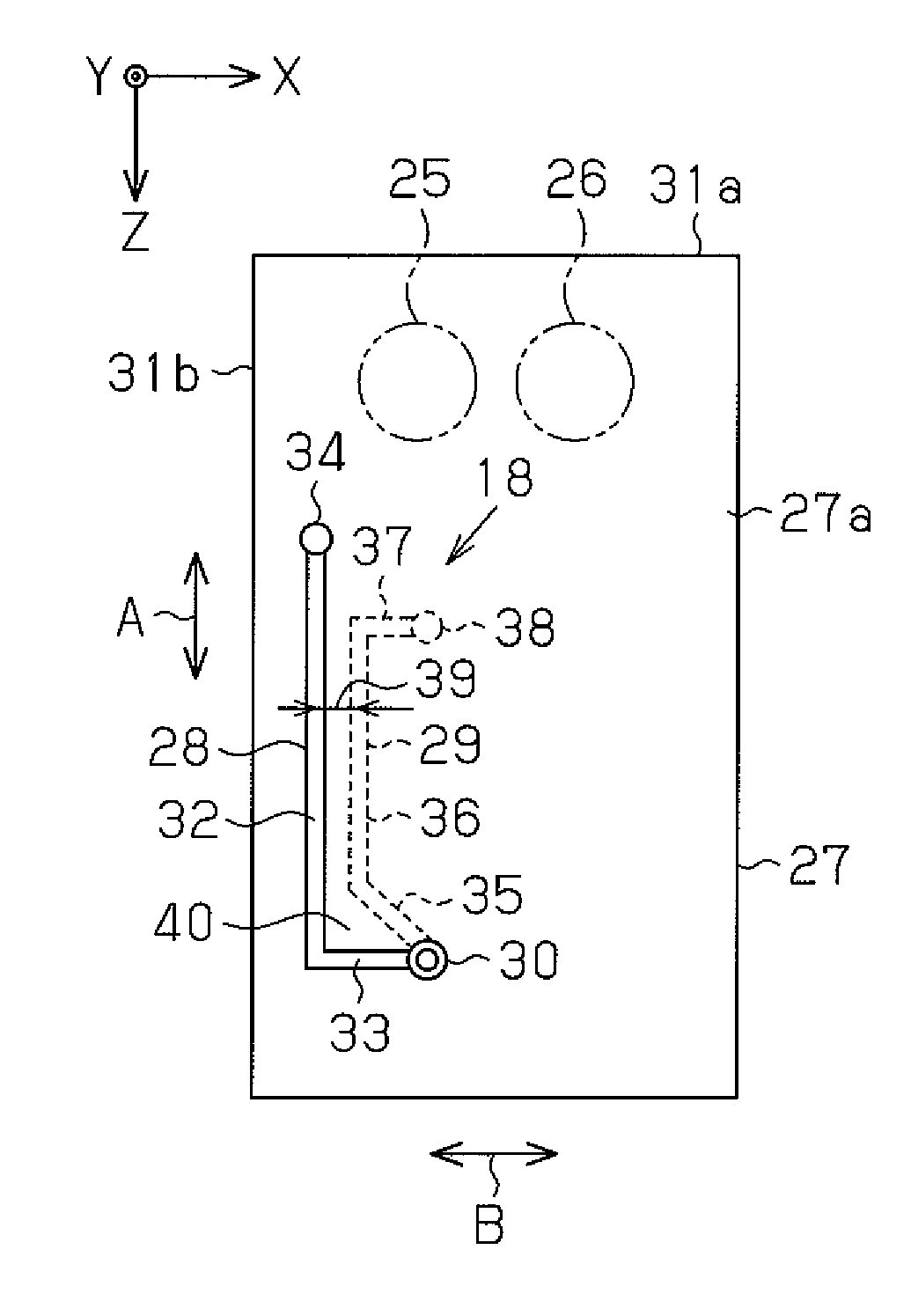
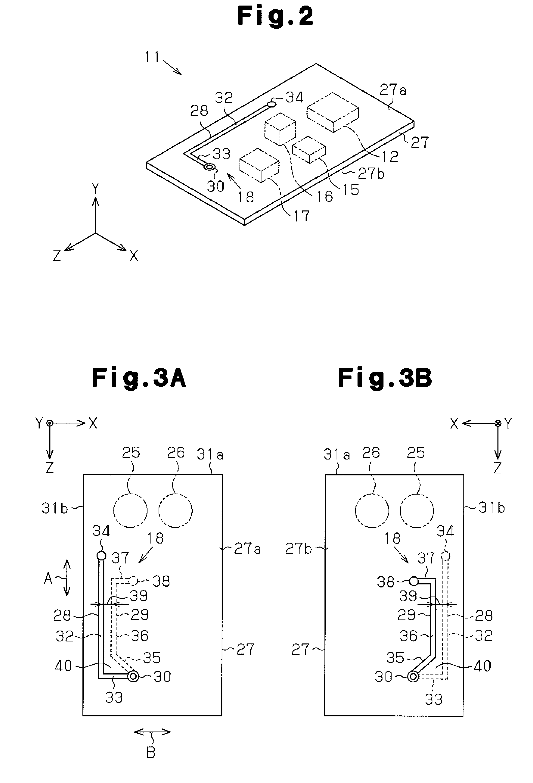
[0018]A preferred embodiment of an antenna structure for a wireless communication device according to a preferred embodiment of the present invention will now be discussed with reference to FIGS. 1 to 5.

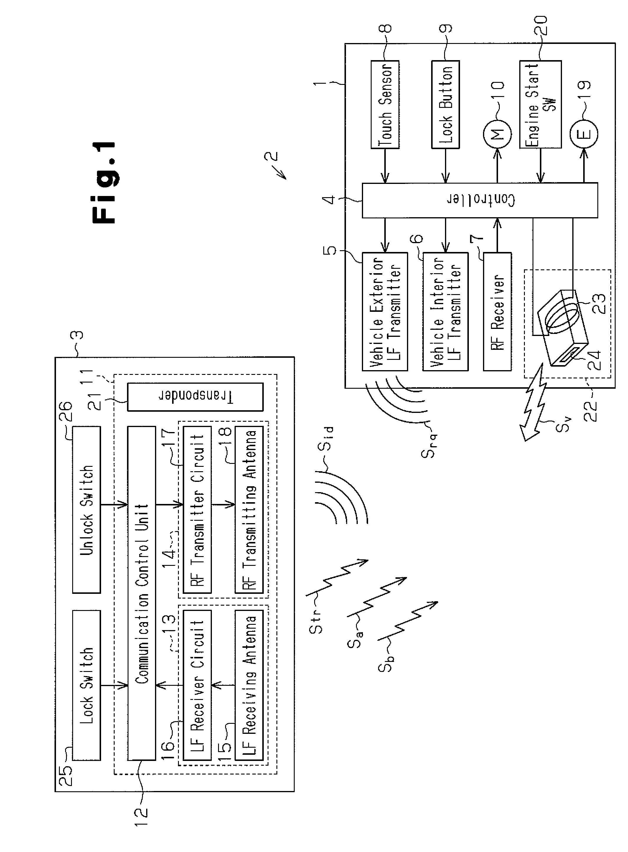
[0019]Referring to FIG. 1, a vehicle 1 is equipped with a hands-free system 2, which locks or unlocks the vehicle doors and starts the engine without the need for performing an operation with a key. The hands-free system 2 transmits a request signal Srq from the vehicle 1. In response to the request signal Srq, a portable device 3 returns an ID code signal Sid, which includes an ID code of the portable device 3. When the ID code of the portable device 3 and an ID code of the vehicle 1 match, the vehicle doors can be locked or unlocked, the starting of the engine is enabled, and the engine may actually be started. The portable device 3 functions as a wireless communication device.

[0020]The hands-free system 2 includes a controller 4, which is located in the vehicle 1 and used to centr...


PUM


Abstract

An antenna structure for a wireless communication device including a substrate having a first surface that supports an electronic component and a second surface opposite to the first surface. The antenna structure includes a first surface pattern formed on the first surface of the substrate. A second surface pattern is formed on the second surface of the substrate. The second surface pattern is at least partially separated from the first surface pattern in a direction perpendicular to a thicknesswise direction of the substrate.

Description

RELATED APPLICATIONS[0001]This application is based upon and claims the benefit of Japanese Application 2007-133259 filed on May 18, 2007, the contents of which are incorporated herein by reference.BACKGROUND OF THE INVENTION[0002]The present invention relates to an antenna structure for a wireless communication device.[0003]Nowadays, many vehicles are equipped with a hands-free system to improve vehicle operation convenience. For example, a hands-free system locks and unlocks vehicle doors, enables the engine to be started, and actually starts the engine. Such type of a hands-free system includes a low frequency (LF) transmitter and a radio frequency (RF) receiver, which are arranged in a vehicle. The hands-free system communicates with a portable device, which is carried by a user (driver) and functions as a key. The LF transmitter intermittently transmits a request signal in a low frequency band. In response to the request signal, the portable device returns an ID code signal in ...

Claims


Application Information

Patent Timeline
Patent Type & Authority Patents(United States)
IPC IPC(8): H01Q1/38B60R25/01B60R25/04B60R25/10B60R25/24E05B49/00H01Q7/00
CPCB60R25/04B60R25/2063B60R25/24H01Q1/38
Inventor IKEYAMA, MASAHIRO
Owner KK TOKAI RIKA DENKI SEISAKUSHO
Why Eureka
Try Eureka