
Method and apparatus for source and receiver side wave field separation

a receiver and source wave technology, applied in seismology, seismology, instruments, etc., can solve the problems of receiver side de-ghosting cannot be performed with ocean bottom cables, conventional methods do not account for source ghosts, and the loss of resolution of acquired seismic data

Inactive Publication Date: 2009-02-10
WESTERNGECO LLC
View PDF12 Cites 15 Cited by
  • Summary
  • Abstract
  • Description
  • Claims
  • Application Information

AI Technical Summary

Benefits of technology

This approach significantly improves the quality of seismic data by reducing the effects of source and receiver ghosts, resulting in enhanced resolution and reduced notches in the seismic data sets, as demonstrated by the combination of over / under marine seismic data.

Problems solved by technology

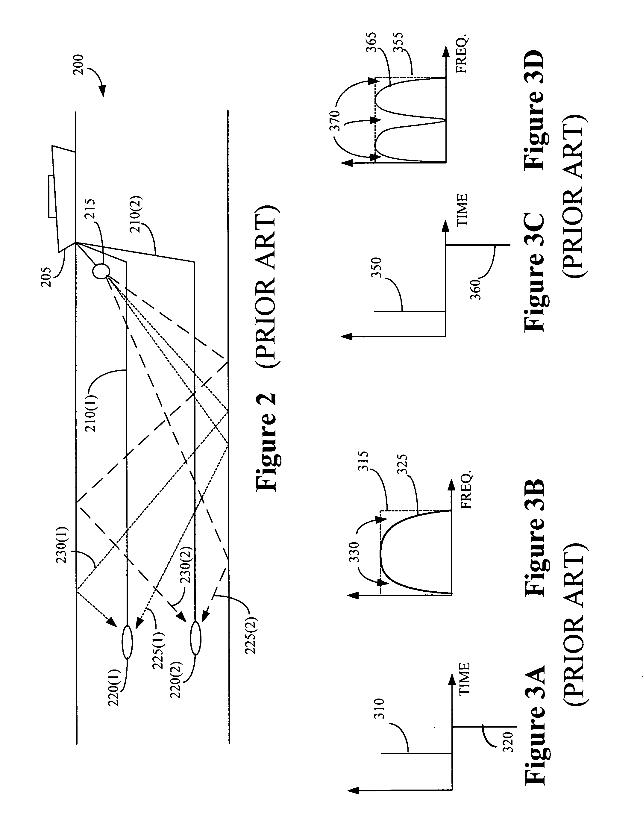
The notches 330, 370 may result in resolution loss in the acquired seismic data.
However, these conventional methods do not account for source ghosts.
Moreover, receiver side de-ghosting cannot be performed with ocean bottom cables, since these cables typically rest on the sea floor and thus cannot be deployed in an over-under configuration.
Consequently, conventional methods of de-ghosting seismic data are not able account for both receiver and source ghosts, as well as the interactions between them, such as the effect of source ghosts on receiver-side seismic data.

Method used


Image

  • Method and apparatus for source and receiver side wave field separation
  • Method and apparatus for source and receiver side wave field separation
  • Method and apparatus for source and receiver side wave field separation

Examples


Embodiment Construction

[0025]Illustrative embodiments of the invention are described below. In the interest of clarity, not all features of an actual implementation are described in this specification. It will of course be appreciated that in the development of any such actual embodiment, numerous implementation-specific decisions should be made to achieve the developers' specific goals, such as compliance with system-related and business-related constraints, which will vary from one implementation to another. Moreover, it will be appreciated that such a development effort might be complex and time-consuming, but would nevertheless be a routine undertaking for those of ordinary skill in the art having the benefit of this disclosure.

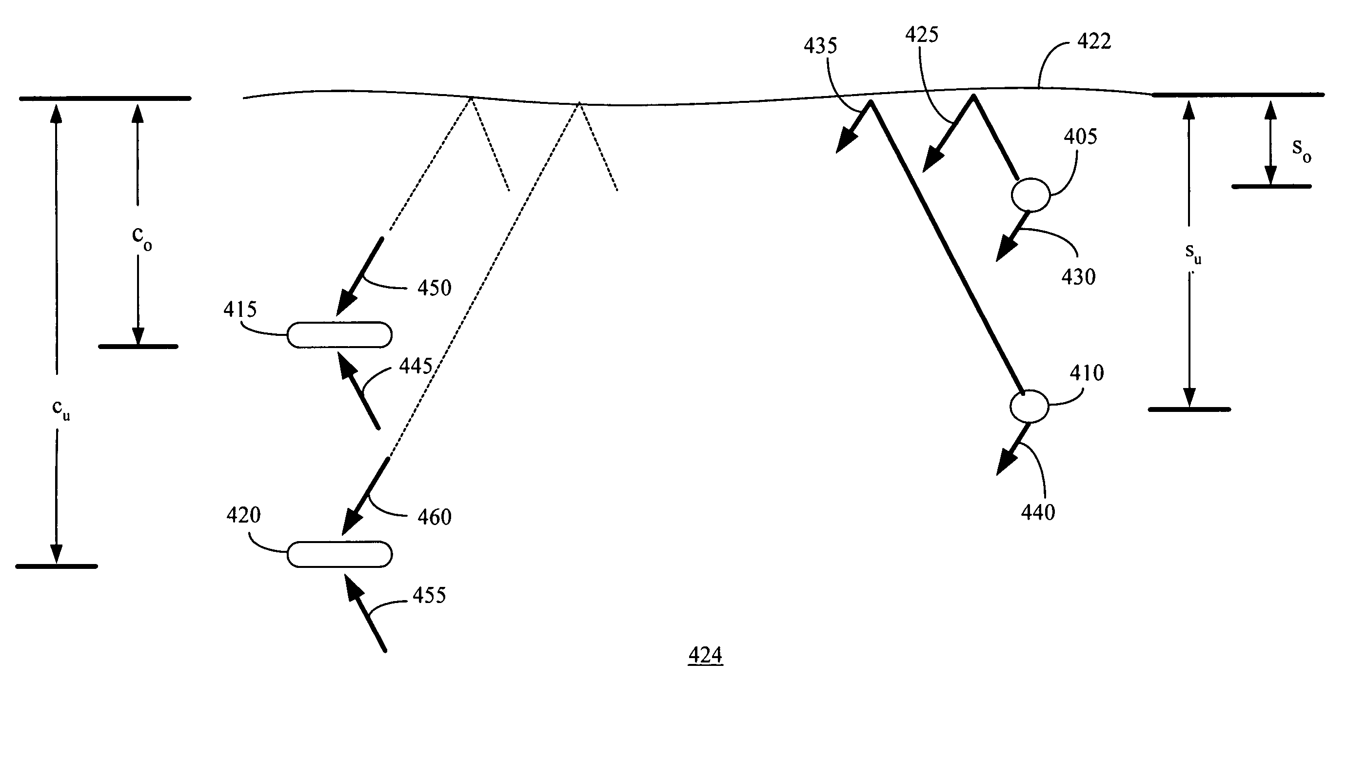
[0026]FIG. 4 conceptually illustrates a marine seismic survey system 400 including two sources 405, 410 and two receivers 415, 420. The sources 405, 410 and receivers 415, 420 are arranged in over / under configurations and are deployed beneath a surface 422 of a body of water 42...


PUM


Abstract

The present invention provides a method and apparatus for wave field separation. The method includes accessing a marine seismic data set acquired by a plurality of receivers deployed at a first plurality of depths in response to a plurality of acoustic signals provided by a plurality of seismic sources deployed at a second plurality of depths and forming at least one de-ghosted marine seismic data set based upon the plurality of seismic data sets.

Description

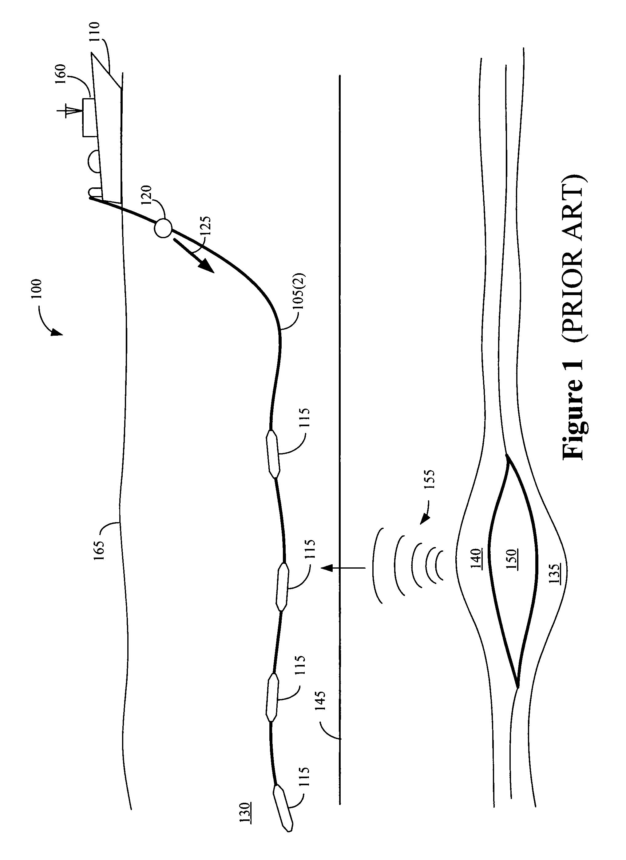
BACKGROUND OF THE INVENTION[0001]1. Field of the Invention[0002]This invention relates generally to marine seismic surveying, and, more particularly, to source and receiver side wave field separation for seismic data acquired in a marine seismic survey.[0003]2. Description of the Related Art[0004]Seismic exploration is widely used to locate and / or survey subterranean geological formations for hydrocarbon deposits. Since many commercially valuable hydrocarbon deposits are located beneath bodies of water, various types of marine seismic surveys have been developed. In a typical marine seismic survey, such as the exemplary survey 100 conceptually illustrated in FIG. 1, marine seismic streamer 105 is towed behind a survey vessel 110. The seismic streamer 105 may be several thousand meters long and contain a large number of sensors 115, such as hydrophones and associated electronic equipment, which are distributed along the length of the each seismic streamer cable 105. The survey vessel...

Claims


Application Information

Patent Timeline
Patent Type & Authority Patents(United States)
IPC IPC(8): G01V1/38
CPCG01V1/364G01V1/3808G01V2210/56G01V1/36G01V1/3817
Inventor GRION, SERGIO
Owner WESTERNGECO LLC
Learn More