Wide field-of-view binocular device, system and kit

a binocular device and wide field of view technology, applied in the field of binocular devices, systems and kits, can solve the problems of not being able to easily miniaturize, heavy crt display, and inability to view sharp images at a closer distance,

Inactive Publication Date: 2009-02-17
MIRAGE INNOVATIONS LTD
View PDF75 Cites 94 Cited by
  • Summary
  • Abstract
  • Description
  • Claims
  • Application Information

AI Technical Summary

Benefits of technology

[0018]According to one aspect of the present invention there is provided an optical device for transmitting light striking the optical device at a plurality of angles defining a field-of-view, the optical device comprising a light-transmissive substrate formed with at least one input optical element and a plurality of output optical elements; the at least one input optical element being designed and constructed to diffract the light into the light-transmissive substrate in a manner such that different portions of the light, corresponding to different portions of the field-of-view, propagate in different directions within the light-transmissive substrate; and the plurality of output optical elements being designed and constructed to complementarily diffract the different portions of the light out of the light-transmissive substrate, thereby to substantially preserve the field-of-view.
[0043]According to a further aspect of the present invention there is provided a method of transmitting light striking light-transmissive substrate at a plurality of angles defining a field-of-view, the method comprising: (a) diffracting the light into the light-transmissive substrate in a manner such that different portions of the light, corresponding to different portions of the field-of-view, propagate in different directions within the light-transmissive substrate; and (b) complementarily diffracting the different portions of the light out of the light-transmissive substrate, so as to substantially preserve the field-of-view.

Problems solved by technology

Unless a person is long-sighted, he may not be able to view a sharp image at a closer distance.
The CRT displays are heavy, bulky and not easily miniaturized.
The active matrix panel uses a transistor to control each pixel, and is more expensive.
Small size real image displays have a relatively small surface area on which to present a real image, thus have limited capability for providing sufficient information to the user.
In other words, because of the limited resolution of the human eye, the amount of details resolved from a small size real image might be insufficient.
For example, such displays have suffered from being too heavy for comfortable use, as well as too large so as to be obtrusive, distracting and even disorienting.
These defects stem from, inter alia, the incorporation of relatively large optics systems within the mounting structures, as well as physical designs which fail to adequately take into account important factors as size, shape, weight, etc.
A common problem to all types of holographic optical elements is their relatively high chromatic dispersion.
This is a major drawback in applications where the light source is not purely monochromatic.
Another drawback of some of these displays is the lack of coherence between the geometry of the image and the geometry of the holographic optical element, which causes aberrations in the image array that decrease the image quality.
New designs, which typically deal with a single holographic optical element, compensate for the geometric and chromatic aberrations by using non-spherical waves rather than simple spherical waves for recording; however, they do not overcome the chromatic dispersion problem.
Moreover, with these designs, the overall optical systems are usually very complicated and difficult to manufacture.
Furthermore, the field-of-view-resulting from these designs is usually very small.
Upatnieks, however, does not teach how the display could transmit a wide field-of-view, or tackle a broad spectrum of wavelengths (for providing color images).
However, the diffractive collimating element of Friesem et al. is known to narrow spectral response, and the low chromatic sensitivity at spectral range of ±2 nm becomes an unacceptable sensitivity at ±20 nm or ±70 nm.
Due to the single optical channel employed by presently known devices, the field-of-view which can be achieved without distortions or loss of information is rather limited.
WO 01 / 95027. to Amitai], these systems are rather bulky, heavily rely on relative positioning and / or relative alignment and are generally less than fully satisfactory.
Any departure from such alignment can have many undesirable consequences including loss of image quality, as perceived by the user, user eye strain or fatigue and nausea.

Method used


Image

  • Wide field-of-view binocular device, system and kit
  • Wide field-of-view binocular device, system and kit
  • Wide field-of-view binocular device, system and kit

Examples


example 1

Monochromatic Configuration for Blue Light

[0268]This example demonstrate the attainable field-of-view when Equation 3 is employed for a wavelength λ=465 nm (blue light), and indices of refraction nS=1.5 for the light-transmissive substrate and nA=1.0 for air, corresponding to a the critical angle is 41.8°.

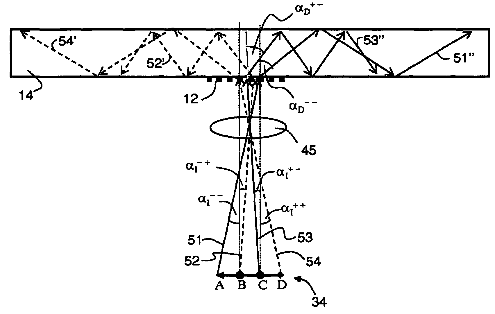
[0269]For a grating period d=430 mn (λ / d>1, see Equation 3), the maximal (negative by sign) angle at which total internal reflection can be occur is 4.67°. In the notation of FIG. 6a, αI+−=−4.67° (see ray 53). However, the positive incidence angle (see ray 51 of FIG. 6a) can be as large as αI−−=23.32°, in which case the diffraction angle is about 80°, which comply with the total internal reflection condition. Thus, in this configuration, each of the attainable asymmetric field-of-views is of |αI++|+αI−−≈28°, resulting in a symmetric combined field-of-view of 2×αI−−≈47°.

example 2

Monochromatic Configuration for Red Light

[0270]This example demonstrate the attainable field-of-view when Equation 4 is employed for a wavelength λ=620 nm (red light) and the refraction indices of Example 1, corresponding to the same critical angle (αc=41.8°).

[0271]Imposing the “flat” requirement and a maximal diffraction angle of 80°, one can calculate that for λ=620 nm the, grating period of Example 1 d=430 nm complies with Equation 4.

[0272]The maximal (positive by sign) angle at which total internal reflection can occur is 2.03°. In the notation of FIG. 6b, αI−+=+2.03° (see ray 52). The negative incidence angle (see ray 54 of FIG. 6b) is limited by the requirement |αD++|c, which corresponds to αI++=−26.22°. Thus, in this configuration, each of the attainable asymmetric field-of-views is of about 28°, resulting in a symmetric combined field-of-view of about 52°.

example 3

Multicolor Configuration

[0273]This example demonstrate the attainable field-of-view when Equation 6 is employed for a spectrum in which the shortest wavelength is λB=465 nm (blue light) and the longest wavelength is λR=620 nm (red light). The refraction indices, the critical angle and the maximal diffraction angle are the same as in Example 2.

[0274]Using Equation 6, one obtains d=438 nm. Further, using Equation 2 one can calculate the asymmetric field-of-views of the blue and red lights.

[0275]Hence for the blue light the first asymmetric field-of-view is [−3.54°, 24.56°], the second asymmetric field-of-view is [−24.56°, 3.54°], resulting in a combined field-of-view of about 49°.

[0276]For the red light, the calculation yield an opposite situation in which the first asymmetric field-of-view is [−24.56°, 3.54°], and the second asymmetric field-of-view is [−3.54°, 24.56°], still resulting in a combined field-of-view of about 49°.

[0277]If a third, intermediate wavelength is present, say ...


PUM


Abstract

A binocular device for transmitting an image into the eyes is provided. The binocular device comprises a first monocular device, for providing one eye with a first asymmetric field-of-view, and a second monocular device for providing another eye with a second asymmetric field-of-view, where the first and second asymmetric field-of-views are mutually complementary to a combined field-of-view, wider than each individual asymmetric field-of-view.

Description

[0001]This is a continuation-in-part of U.S. patent application Ser. No. 10 / 896,865, filed Jul. 23, 2004. This application also claims the benefit of priority from U.S. Provisional Patent Application No. 60 / 632,303, filed Dec. 2, 2004.FIELD AND BACKGROUND OF THE INVENTION[0002]The present invention relates to a device, system and kit, and, more particularly, to a binocular device, system and kit having a wide field-of-view which is capable of providing monochrome or multicolor images.[0003]Miniaturization of electronic devices has always been a continuing objective in the field of electronics. Electronic devices are often equipped with some form of a display, which is visible to a user. As these devices reduce in size, there is an increase need for manufacturing compact displays, which are compatible with small size electronic devices. Besides having small dimensions, such displays should not sacrifice image quality, and be available at low cost. By definition the above characterist...

Claims


Application Information

Patent Timeline
Patent Type & Authority Patents(United States)
IPC IPC(8): G02B23/00G02B27/14
CPCG02B23/18G02B27/0172G02B6/0016G02B6/0038G02B2027/011G02B2027/0116G02B2027/0123G02B2027/0138G02B2027/0174G02B2027/0178G02B5/18G02B23/00
Inventor NIV, YEHUDANIVON, UZIACOHEN, TAL
Owner MIRAGE INNOVATIONS LTD
Why Eureka
Try Eureka