LED light source with field-of-view-controlling optics

a technology of field-of-view control and led light source, which is applied in the direction of discharge tube luminescnet screens, identification means, instruments, etc., can solve the problems of excess off-angle and waste of light emitted by led displays at angles outside this rang

Inactive Publication Date: 2003-08-05
TELEDYNE LIGHTING & DISPLAY PRODS
View PDF94 Cites 140 Cited by
  • Summary
  • Abstract
  • Description
  • Claims
  • Application Information

AI Technical Summary

Benefits of technology

Another aspect of the invention comprises a method of manipulating an LED's light to provide Lambertian emission through a requisite range of viewing angles. The method includes the step of collecting light emitted from plural side surfaces of a light-emitting diode and redirecting the light so that it approximates the emission pattern of a single Lambertian surface. The divergence of collected light is reduced in a plane orthogonal to an opposing pair of the plural sides. The collected light is refracted after reducing the divergence.
Still another aspect of the invention comprises a method of shaping the output of a light-emitting diode having a front and a plurality of sides that emit light. This method includes the step of collecting light emitted from the sides and redirecting the light to simulate light produced by a single substantially Lambertian surface. In addition, reflectors are used to reduce the divergence of the beam in one direction, preferably the vertical, to a limited range of angles, while maintaining a substantially Lambertian fall-off within a substantial portion of said limited range.

Problems solved by technology

Also, although the LED's radiate in a wide range of directions, the displays are typically viewed by an audience that is located within a vertically confined region, such that the audience views the displays from a limited range of vertical angles.
Light emitted by the LED display at angles outside this range is wasted, since it does not reach any viewers.
The bullet-lens configuration of the prior art, however, is not an Lambertian emitter and instead provides reduced or excess off-angle brightness.

Method used


Image

  • LED light source with field-of-view-controlling optics
  • LED light source with field-of-view-controlling optics
  • LED light source with field-of-view-controlling optics

Examples


Embodiment Construction

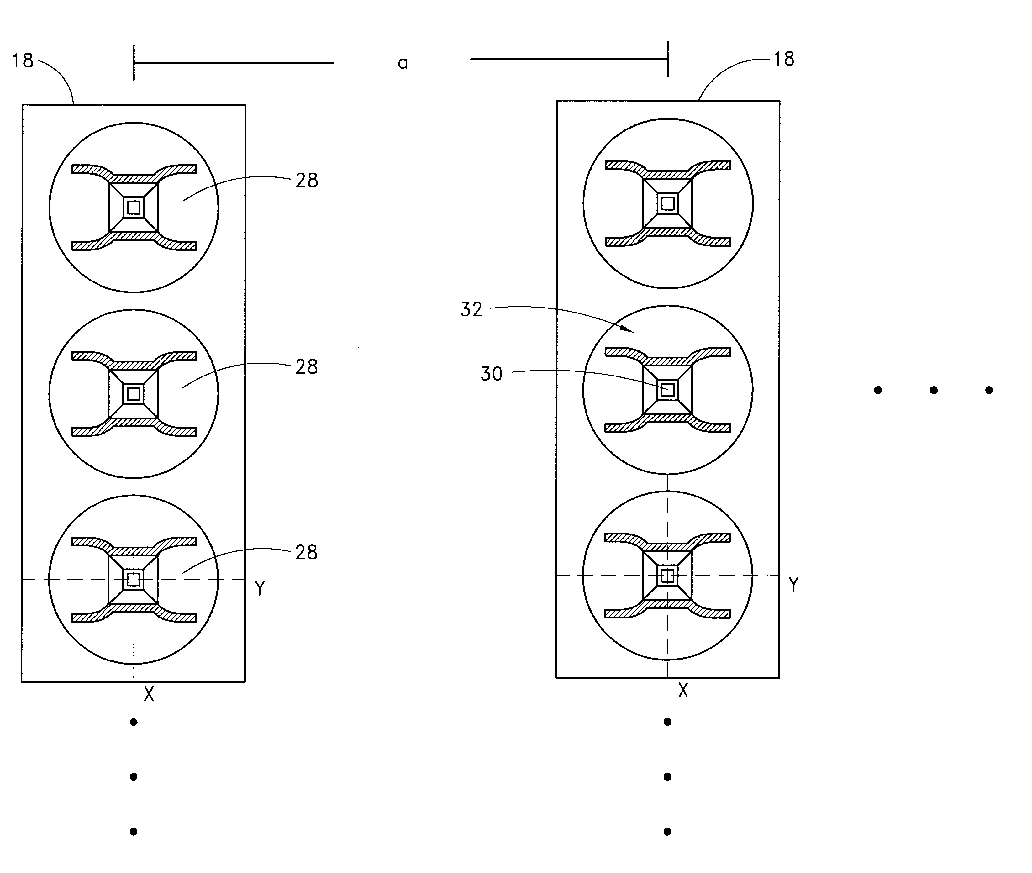
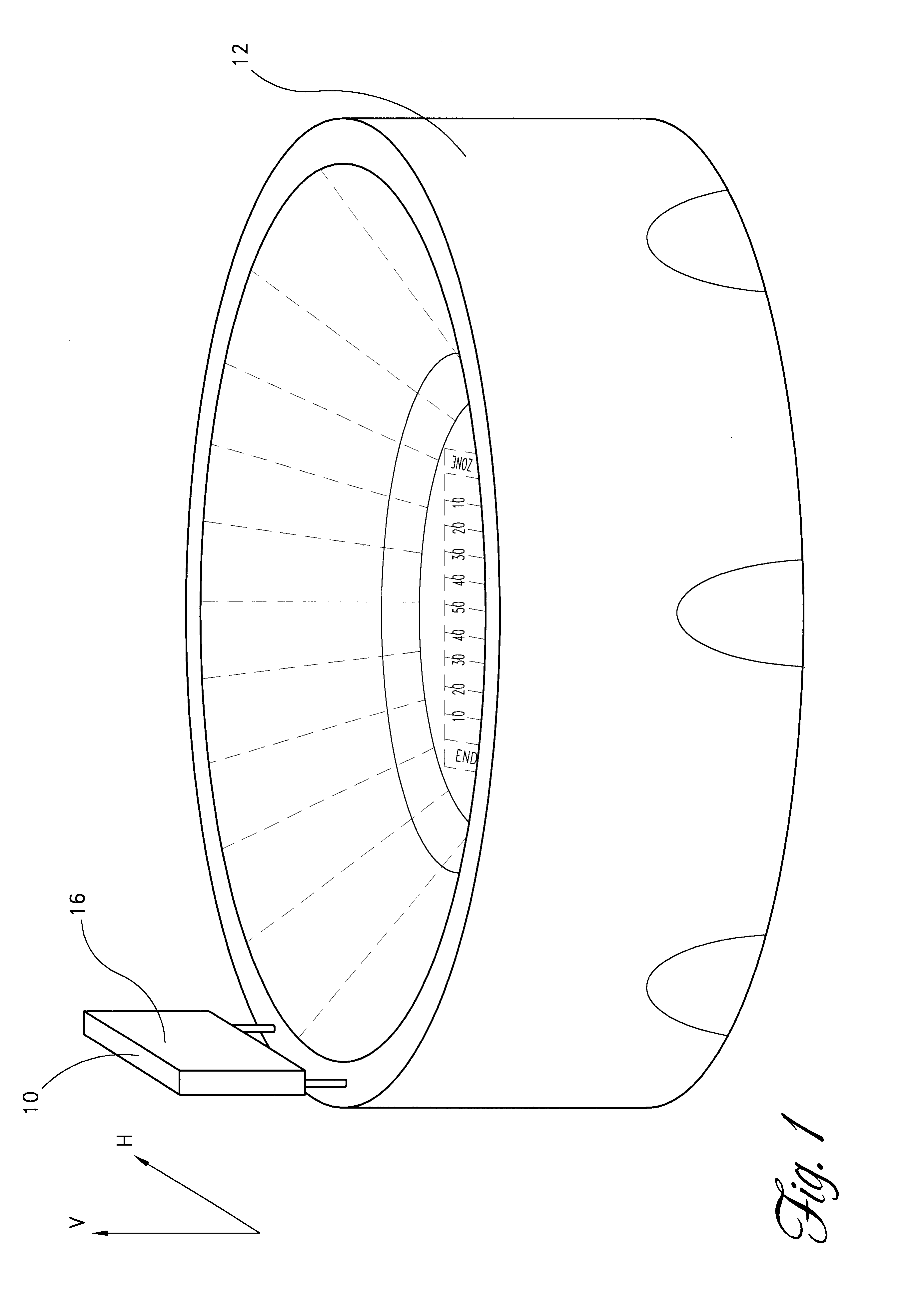
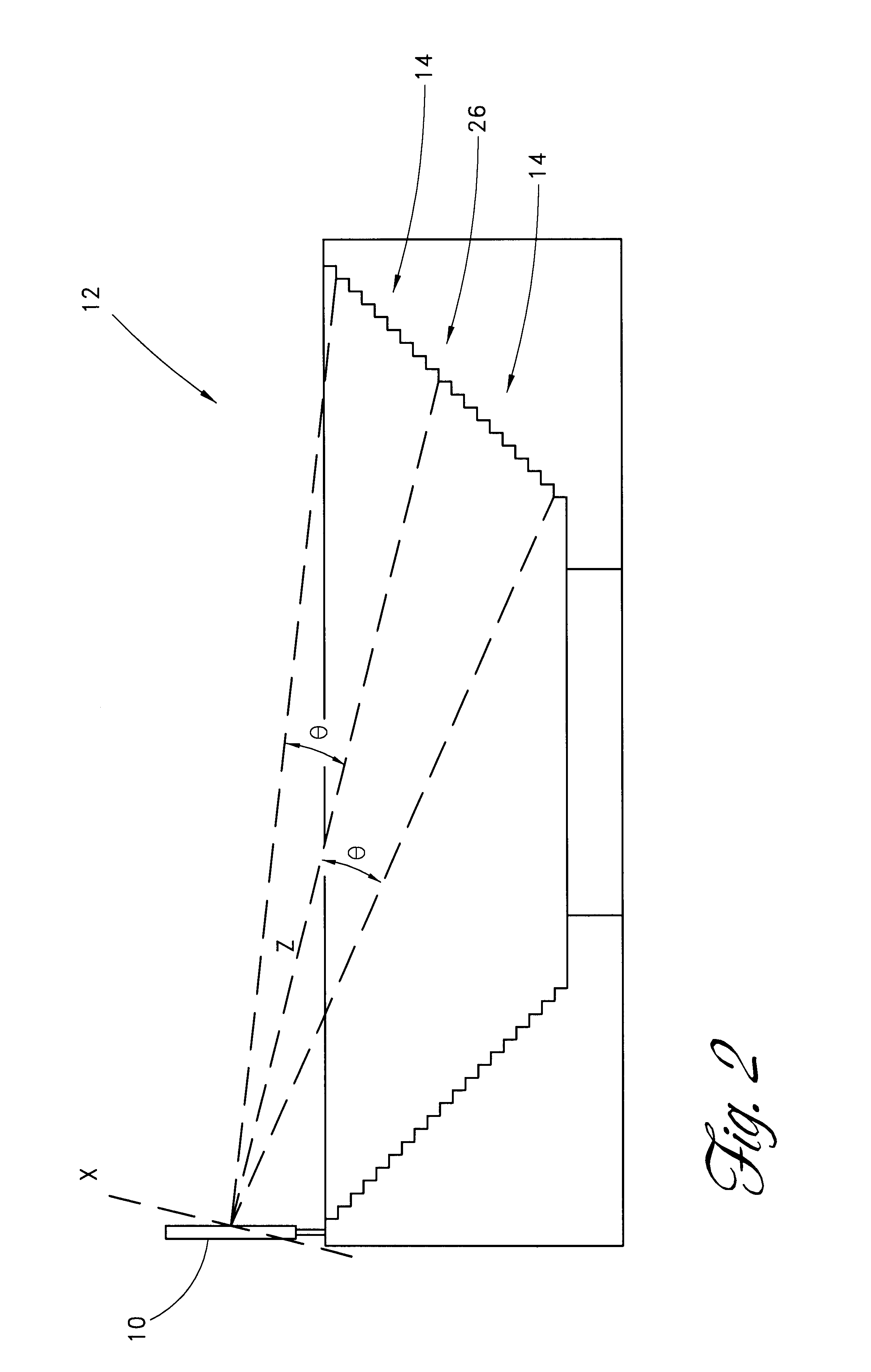
As shown in FIGS. 1-3, a large-scale color light-emitting diode (LED) display 10 can be located in a stadium 12 for viewing from a specific section of seating 14. Only one side 16 of the display 10, the front, is visible to the audience. As shown in FIGS. 4-7, this front side 16 of the display 10 comprises a rectangular array of pixels 18 each having a face 20 of length, L, and width, W. The pixels 18 are arranged in rows 22 and columns 24 parallel to vertical (upward) and horizontal (sideways) directions in the stadium. Axes marked V and H in FIG. 1 designate these vertical and horizontal directions.

Another frame of reference more closely associated with the orientation of the pixels 18 in the array 10 is provided by an x, y, z, coordinate system shown in FIGS. 2-7. In this coordinate system, the row 22 of pixels 18 coincides with the y-axis, which is aligned with the horizontal direction, H. In contrast, the x-axis, which is parallel to the pixel length, is not aligned with the ve...


PUM


Abstract

Pixels for a large video display which employs solid-state emitters, such as colored light emitting diodes, as light source are formed by outfitting each colored solid state emitter within the pixel with an individually tailored miniature intensity-enhancing optical system. Each of these miniature optical systems comprises a set of four wide field-of-view Lambertian reflectors 34, a pair of narrow field-of-view Lambertian reflectors 36, and a beam-shaping lens 38. The miniature intensity-enhancing optical system can be specifically designed to restrict emission in the vertical field-of-view, while providing a Lambertian intensity dependence throughout an unrestricted horizontal view. For example, the field-of-view in the vertical direction may be limited to about .+-.30.degree. while the field-of-view is about .+-.90.degree. in the horizontal direction.

Description

BACKGROUND OF THE INVENTIONThe present invention relates to light-emitting diode (LED) displays and, more specifically, to pixel designs for LED displays.Large full-color displays for viewing video images in daylight have become increasingly common in the United States and Japan, for example, in sports stadiums and for advertisements on buildings. These large displays comprise hundreds of thousands of pixels that can be arranged in a similar fashion as those in conventional color televisions. Each pixel includes a red, green, and blue light-emitting diode (LED), because they can in combination produce all hues. The three colored diodes in a pixel comprise a triad and are situated in close proximity to each other in a single package, the triad-package. This close proximity ensures that they are not separately visible to viewers, who see only the hue the light-emitting diodes (LEDs) produce in combination. In prior art designs such as those manufactured by Nichia, each triad has a sin...

Claims


Application Information

Patent Timeline
Patent Type & Authority Patents(United States)
IPC IPC(8): G09F9/33H01L33/48H01L33/58H01L33/60
CPCG09F9/33Y10S362/80H01L2224/48091H01L2224/73265H01L2924/00014
Inventor PARKYN, WILLIAM A.PELKA, DAVID G.
Owner TELEDYNE LIGHTING & DISPLAY PRODS
Why Eureka
Try Eureka