
Birefringent interferometer

Inactive Publication Date: 2002-07-16
CAMBRIDGE RES & INSTR
View PDF18 Cites 137 Cited by
  • Summary
  • Abstract
  • Description
  • Claims
  • Application Information

AI Technical Summary

Benefits of technology

The assembly forms an imaging spectrometer that is simple, economical, and capable of precise spectroscopic analysis. It provides nearly diffraction-limited image quality, and can be built using two-dimensional pixelated detectors such as CCD and CID sensors. This arrangement yields spectra for every point in a complex scene, using very simple equipment and conventional imaging detectors.
It is possible to incorporate fixed retarders such as quartz or calcite waveplates into the polarization interferometer, to achieve a greater range of OPD adjustment and realize higher spectral resolution. Several cells may be combined in series without significantly degrading the image quality, OPD selection, or off-axis properties. The invention preferably includes a reference beam, such as from a laser diode, to provide in-situ monitoring of the OPD.

Problems solved by technology

An optical path difference is developed between the paths, which results in constructive or destructive interference, depending on the wavelength of light and on the optical path difference (OPD).
This involves the motion or rotation of one or more optical elements, such as mirrors or windows, which leads to high cost and complexity given the need to control the OPD variation to a small fraction of a wavelength of light.
However, this normally results in a limited range of adjustment, as the modulation range of most electro-optic modulators is limited to approximately one wavelength of light.
This is especially common in mechanically-varied systems, or in systems which provide a large change in OPD, for which it is otherwise difficult to determine the exact OPD achieved by the system.
These systems are generally complex, mechanically delicate, and thermally sensitive.
Most FTS systems provide a spectrum for the incident beam as a whole, and cannot provide spectra for each point in a two-dimensional input scene; thus they are termed non-imaging spectrometers.
A related problem arises because the sensor has discrete pixels: as the OPD is varied, the sensor location corresponding to a given scene location will move from being within a given pixel, to the adjacent region which lies between pixels.
This causes image smear, and mixing of the spectral content of adjacent pixels.
Further, it is not easy to acquire images of objects that move between successive exposures, since registration error cannot be corrected by a simple Cartesian shift.
However, there are a few severe limitations.
This is 600.times. too slow to use in Buican's instrument.
However, the need for scanning means subvert the inherent simplicity and ruggedness that this system offers.
The system is not capable of spectral analysis, nor of identifying plural wavelengths in an optical beam, as the only information available is the number of maxima and minima during an overall retardance excursion; hence only the mean-center wavelength is sensed.
The reliance on a Michelson design renders the instrument thermally-sensitive, and requires fabrication of many precision optical surfaces; these concerns are in no way ameliorated through the use of liquid crystal elements.
However, construction of an instrument with high resolution is difficult, due to mismatch between cells, thermal drift, and component tolerances.
The same factors limit the wavelength accuracy of a spectrometer built on these principles.
But they point out that their system suffers from strong dependence on incident angle, leading to a severely limited field-of-view, which is asymmetric and not easy to study or remove by post-processing of the interferograms.
Further, the system is prone to drift and does not produce a stable OPD as the ambient temperature is varied.
Achieving precisely even OPD spacing with this system would require fabrication of the fixed retarders to exacting tolerances, which is costly.
Yet this does not ameliorate the problems brought on by discrete OPD steps.
Since it does not provide the same OPD for all wavelengths (even in the absence of dispersion), but rather provides a constant degree of polarization rotation independent of wavelength, it is not clear whether any meaningful spectral information is gained from the use of this element.
So, while interferometers, PEM-based polarization interferometers, AOTFs, LCTFs and various liquid crystal arrangements have been taught by the prior art, all have severe limitations.
Those which provide for spectral imaging by interference means such as Michelson, Sagnac, or other interferometers suffer from high cost and complexity.
PEM systems are not compatible with imaging detectors, and require a scanning mechanism if an image is sought.
AOTFs and LCTFs have low throughput and, since they reject all light that lies outside of their passband, fail to make use of all the information in the incident beam.
Coherence detectors and wavelength detectors do not provide spectral data for non-monochromatic signals.
Prior-art liquid crystal interferometers do not provide a useful field-of-view, or are not thermally rugged, or do not provide continuously variable OPD.
None provides a rugged, economical, precise means for spectral imaging.
Image quality is essentially diffraction-limited.

Method used


Image

  • Birefringent interferometer
  • Birefringent interferometer
  • Birefringent interferometer

Examples


Embodiment Construction

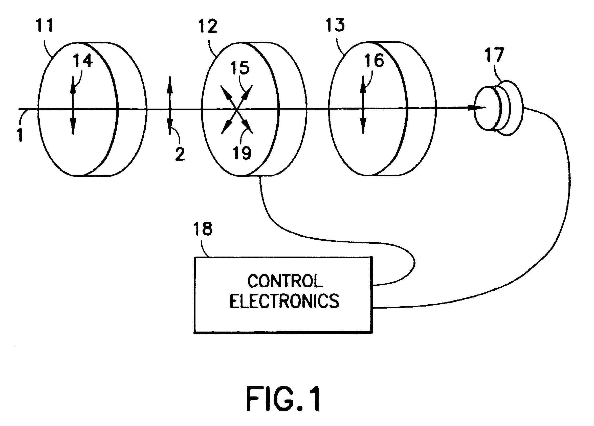
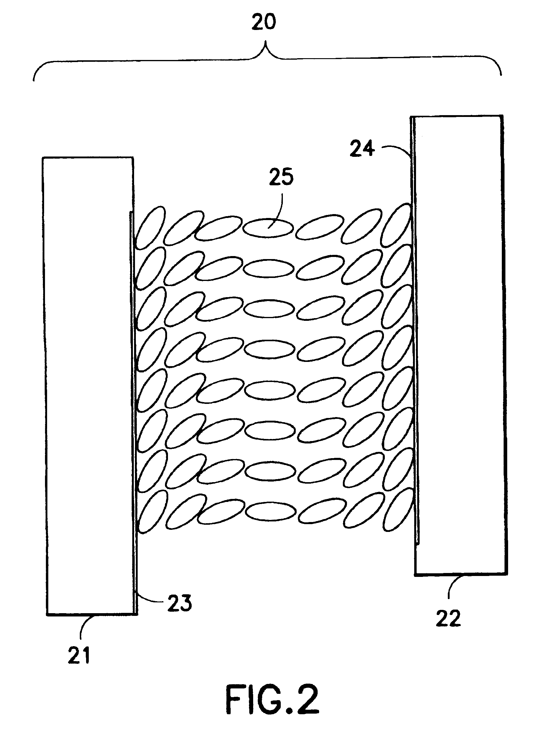
The invention is an interferometer, consisting of a liquid crystal means for adjusting optical retardance over a range of one wavelength or more, in combination with entrance and analyzer polarizers, a detector, and control electronics. If the incident light is suitably polarized, the entrance polarizer may be omitted.

The retardance produces an OPD between the optical component which is polarized along the ordinary axis of the liquid crystal material, and the component which is polarized along the extra-ordinary axis. These components are made to interfere at the analyzer polarizer, in analogy with a conventional two-beam interferometer such as a Michelson interferometer. It is worth noting, however, that since recombination is achieved without use of beamsplitters, the present invention does not suffer the 50% efficiency loss associated with conventional interferometers.

In designing an instrument according to the present invention, one must provide sufficient OPD range to achieve t...


PUM


Abstract

A birefringent interferometer system is described which uses nematic liquid crystal cells to produce variable optical path differences (OPD) between light of different polarization states that are interfered at a polarizing analyzer. Fixed retarders may also be incorporated to extend the range of OPD. The interferometer provides wide field-of-view, continuously variable path difference over a large range, and an on-board monitor of OPD for ensuring accurate settings of path difference, and hence, an accurate wavelength scale in the spectra produced by the apparatus. The system can further incorporate additional polarizing optics so it responds equally well to light of any incident polarization state without loss of efficiency.

Description

1. Field of the InventionThe field of the invention is spectral imaging, specifically spectral measurement which utilizes optical interference to determine spectral content, and which is capable of determining the spectral content at every point in a one- or two-dimensional image or scene.2. Description of the Related ArtOptical interference is widely used in instruments such as the Michelson interferometer, the Mach-Zender interferometer, the Twyman-Greene interferometer, the Sagnac interferometer, and others. These divide incident light into two or more beams traveling along different paths, which are then recombined. An optical path difference is developed between the paths, which results in constructive or destructive interference, depending on the wavelength of light and on the optical path difference (OPD). The intensity pattern resulting from this interference is termed an interferogram. By observing the interferogram while varying the path difference, one can deduce the wave...

Claims


Application Information

Patent Timeline
IPC IPC(8): G01B9/02G01J3/45G01J9/02G01J3/447G01J3/453G01J3/28G01J9/00
CPCG01J3/447G01J3/453G01J9/02G01J3/2823
Inventor MILLER, PETER J.
Owner CAMBRIDGE RES & INSTR
Learn More