Electro-optical foveated imaging and tracking system

a tracking system and optical imaging technology, applied in the field of optical imaging and tracking systems, can solve the problems of inaccurate adjustment of fine imaging systems, poor overall performance, drift, etc., and achieve the effect of high spatial resolution

Inactive Publication Date: 2011-07-05
NEW SPAN OPTO TECH
View PDF8 Cites 154 Cited by
  • Summary
  • Abstract
  • Description
  • Claims
  • Application Information

AI Technical Summary

Benefits of technology

[0009]It is therefore an object of the present invention to provide an E / O imaging sensor that has wide field-of-view for global situation awareness and high spatial resolution at region of interest for object detection and discrimination.
[0010]It is another object of the present invention to reduce data communication bandwidth between photo electronic chip and on board processor and between sensor platform and remote control station.

Problems solved by technology

Optical imaging lenses of both human eye and E / O imaging system could have very powerful resolution capability; however, the later has much poorer overall performance.
To image a wide FOV scene, it would be necessary to combine vast amount of individual images into a giant mosaic due to the limited format size of a conventional imaging detector device.
The shortcomings are that the adjustment of the fine imaging system is mechanical, which is subject to problems of accuracy, vibration, calibration, drift, and unwanted resonance.
This results in a complex system with slow response.
However, when these imaging arrays grow in pixel number for higher resolution, very strong onboard processing and high communication bandwidths will also be required to acquire the image and / or transmit the image data between platforms.
There will be a limitation for applications in small payload platforms that require low cost, compact packaging and low power consumption.
Based on above discussions, there are mainly two constraints in realization of high resolution, large coverage and fast frame rate imaging sensor, which are sensor pixel numbers and data link bandwidth.

Method used


Image

  • Electro-optical foveated imaging and tracking system
  • Electro-optical foveated imaging and tracking system
  • Electro-optical foveated imaging and tracking system

Examples


Embodiment Construction

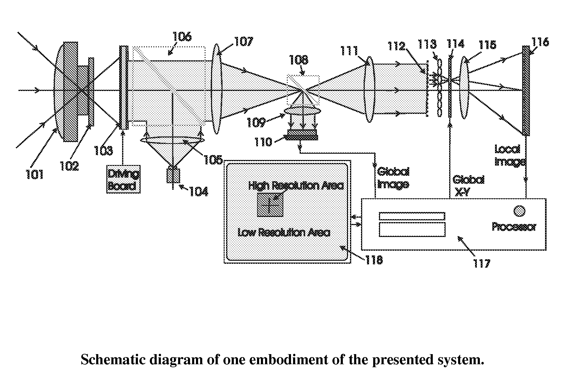
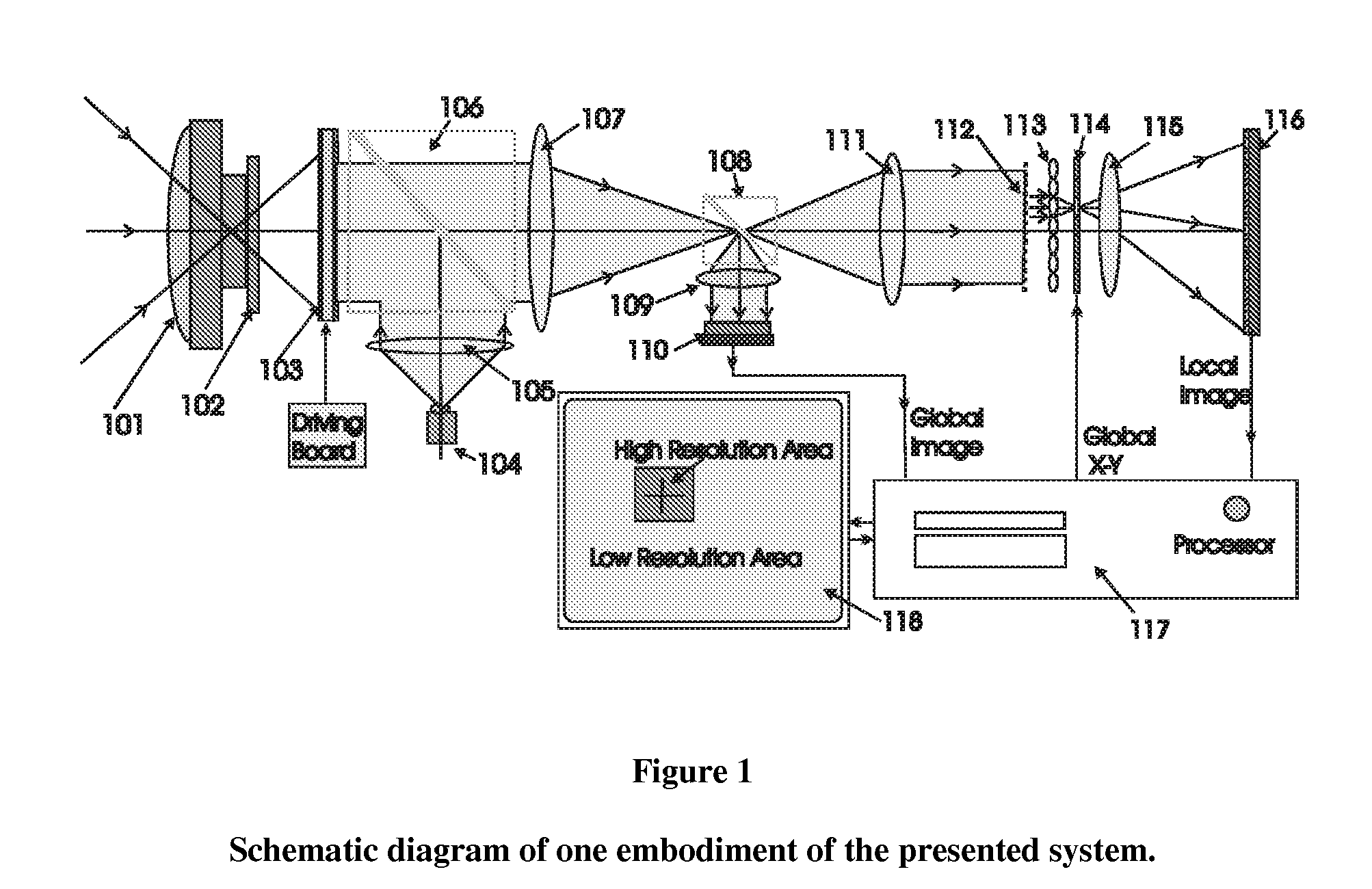
[0019]This invention presents a new sensor system with reconfigurable zooming ability similar to mimic foveal vision of the eye to acquire wide FOV global scene and high-resolution on interest local regions. FIG. 1 is a schematic diagram of one embodiment of the presented foveated imaging and tracking system. It consists of four main portions: (1) wide FOV imaging foreoptics; (2) global coarse image acquisition subsystem; (3) local high resolution images generation and acquisition subsystem, and (4) image processing and accurate target locating subsystem.

[0020]The remote scene is imaged by a wide FOV camera lens 101 designed for the desired wavelength band. For example, for imaging and tracking hot objects, an IR camera lens can be adopted. A proper optical filter 102 is used to transmit wanted spectral band and reflect / eliminate unwanted spectral band. By proper optical imaging system design, a high-resolution image will be presented at the write-in surface of an optically addresse...


PUM


Abstract

Conventional electro-optical imaging systems can not achieve wide field of view (FOV) and high spatial resolution imaging simultaneously due to format size limitations of image sensor arrays. To implement wide field of regard imaging with high resolution, mechanical scanning mechanisms are typically used. Still, sensor data processing and communication speed is constrained due to large amount of data if large format image sensor arrays are used. This invention describes an electro-optical imaging system that achieves wide FOV global imaging for suspect object detection and local high resolution for object recognition and tracking. It mimics foveated imaging property of human eyes. There is no mechanical scanning for changing the region of interest (ROI). Two relatively small format image sensor arrays are used to respectively acquire global low resolution image and local high resolution image. The ROI is detected and located by analysis of the global image. A lens array along with an electronically addressed switch array and a magnification lens is used to pick out and magnify the local image. The global image and local image are processed by the processor, and can be fused for display. Three embodiments of the invention are described.

Description

FIELD OF THE INVENTION[0001]The present invention relates to optical imaging and tracking systems and more particularly to an optical imaging architecture that mimics bio-vision to achieve panoramic monitoring for situation awareness and local high spatial resolution for revealing object details.BACKGROUND OF THE INVENTION[0002]There are varieties of electro-optical (E / O) imaging systems used in commercial and military fields for reconnaissance and surveillance. For optimal status awareness and target discrimination, images acquired using various imaging detectors with sufficient target details and wide field of view (FOV) are necessary.[0003]Similar to the human eye, an E / O imaging system also consists of optical imaging lens, photo sensing array and image receiving and processing unit. Optical imaging lenses of both human eye and E / O imaging system could have very powerful resolution capability; however, the later has much poorer overall performance. The basic reason is that the h...

Claims


Application Information

Patent Timeline
Patent Type & Authority Patents(United States)
IPC IPC(8): H04N5/262
CPCG06K9/3241G06K9/748G06V10/255G06V10/92
Inventor YANG, JIANWEN
Owner NEW SPAN OPTO TECH
Why Eureka
Try Eureka