Boil-off gas condensing assembly for use with liquid storage tanks

a gas condensing and liquid storage tank technology, applied in the direction of container filling under pressure, lighting and heating apparatus, container discharging methods, etc., can solve the problem of reversing the flow through the condensate lin

Active Publication Date: 2009-02-24
CB&I STS DELAWARE LLC
View PDF10 Cites 36 Cited by
  • Summary
  • Abstract
  • Description
  • Claims
  • Application Information

AI Technical Summary

Problems solved by technology

Such conditions might result in a reversal of flow through the condensate line.

Method used


Image

  • Boil-off gas condensing assembly for use with liquid storage tanks
  • Boil-off gas condensing assembly for use with liquid storage tanks
  • Boil-off gas condensing assembly for use with liquid storage tanks

Examples


Embodiment Construction

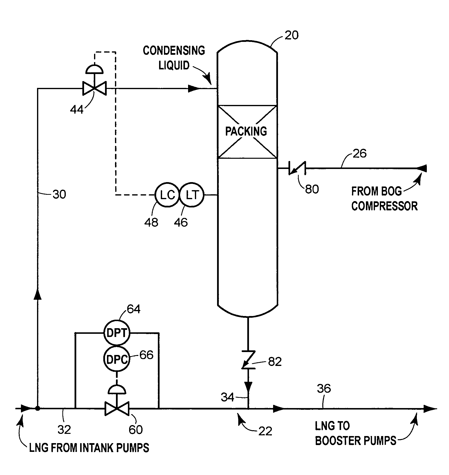
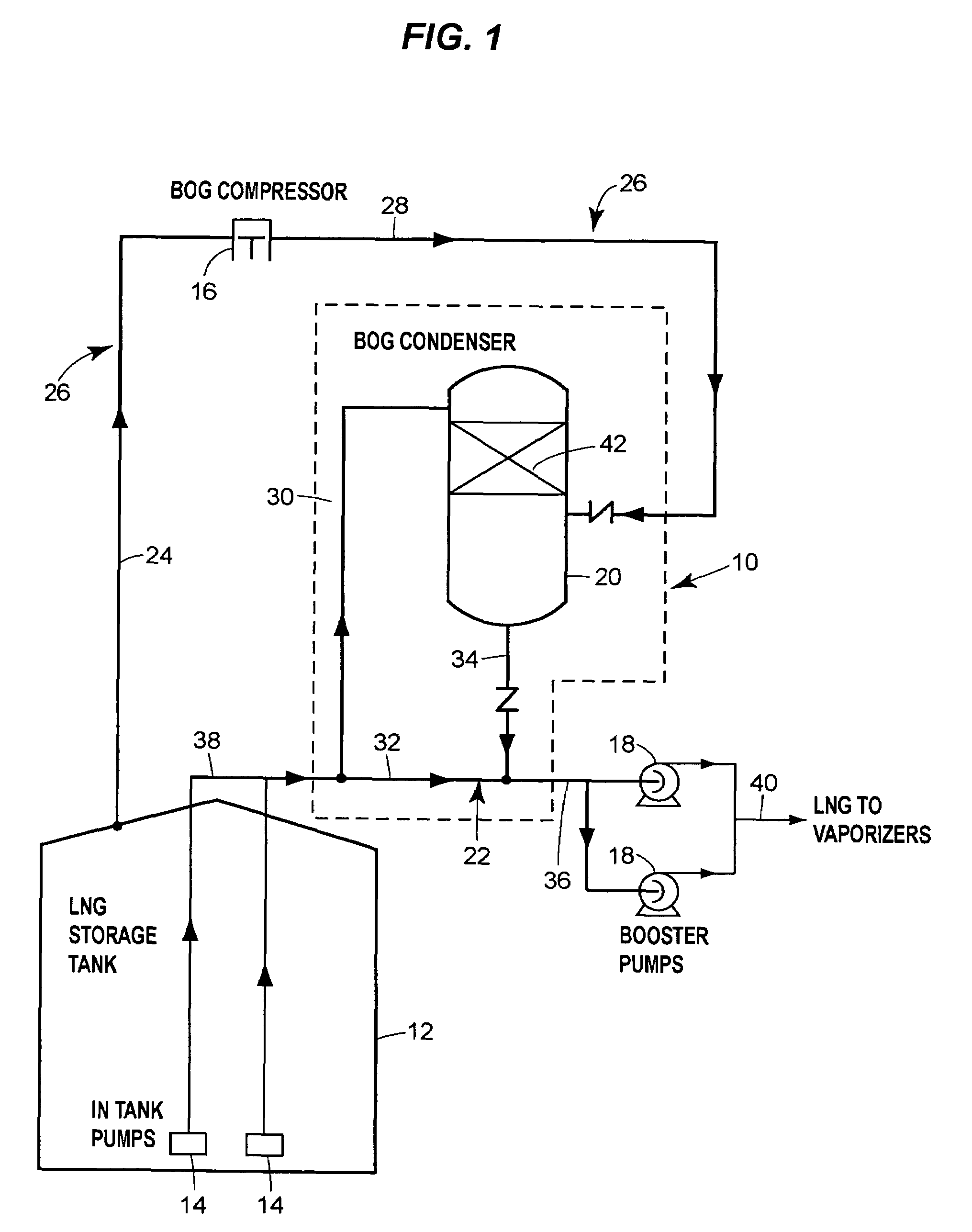
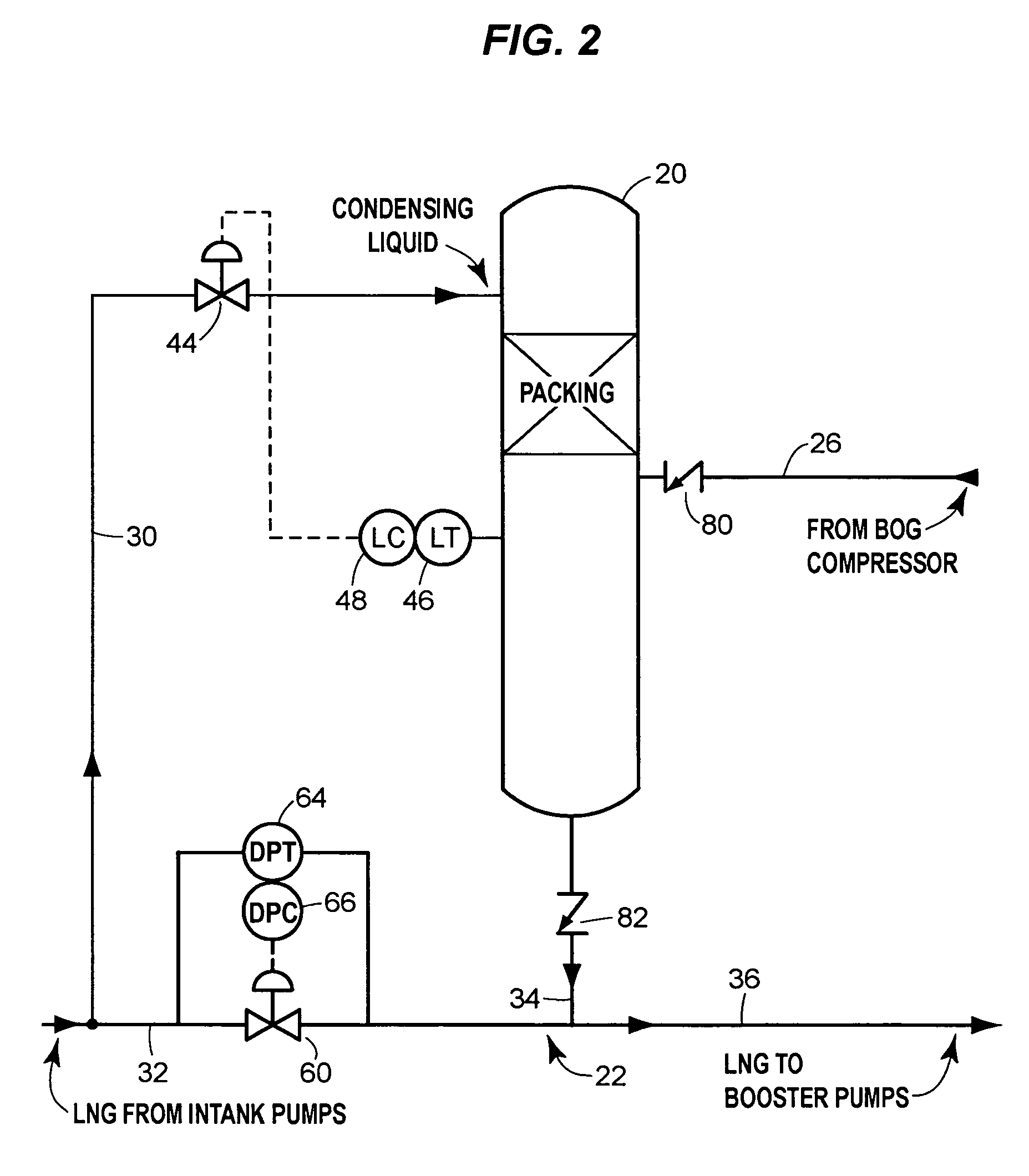
[0018]The condensing assembly 10 illustrated in FIG. 1 is connected to various components of an LNG import terminal. The LNG terminal includes an LNG storage tank 12 that has one or more internal or external low-stage pumps 14, a BOG compressor 16, high-pressure booster pumps 18, and a BOG condenser 20. An inter-stage liquid send-out line 22 connects the low-stage pumps 14 to the booster pumps 18. Between the pumps, the liquid send-out line 22 operates essentially at the discharge pressure of low-stage pumps 14.

[0019]As is known, BOG from the storage tank 12 is typically at a low pressure, and can be boosted to an inter-stage pressure by the BOG compressor 16. A low-stage BOG line segment 24 of a BOG line 26 delivers BOG from the LNG storage tank 12 to the BOG compressor 16. An inter-stage BOG line segment 28 then delivers compressed BOG from the compressor to the condenser 20.

[0020]As with prior systems, liquid send-out from the storage tank 12 is used to condense the compressed BO...


PUM


Abstract

The assembly includes a boil-off gas line that carries storage tank boil-off gas to a condenser that uses condensing liquid from the liquid send-out line to condense the gas. A level control valve on the condensing liquid line actively controls the flow of condensing liquid based on the liquid level in the condenser. A check valve prevents liquid from the send-out line from flowing into the condenser through the condensate line that discharges condensate from the condenser to the send-out line.

Description

CROSS-REFERENCE TO RELATED APPLICATIONS[0001]Not applicable.BACKGROUND OF THE INVENTION[0002]This invention relates generally to liquefied natural gas (LNG) systems. More specifically, it relates to arrangements for condensing boil-off gas from an LNG storage tank and condensing the gas into a send-out stream.[0003]LNG is stored in storage tanks throughout the world. It is typically stored in liquid form at low pressure and cold temperatures, and is pumped to a high pressure before being vaporized and sent out through a natural gas pipeline or distribution system. The pumping operation typically involves a set of low-stage pumps (usually located in the storage tank) that pump the liquid to an inter-stage pressure and a set of high-stage booster pumps (located outside the storage tank).[0004]Boil-off gas (BOG) is the result of heat input into a storage tank that causes some of the stored liquid to vaporize. It can also include vapor displaced by liquid when the tank is filled. Boil-o...

Claims


Application Information

Patent Timeline
Patent Type & Authority Patents(United States)
IPC IPC(8): F25J1/00F17C3/10
CPCF17C5/06F17C9/02F17C13/025F17C2221/033F17C2223/0161F17C2223/033F17C2223/043F17C2223/047F17C2225/0123F17C2225/035F17C2227/0135F17C2227/0178F17C2227/0185F17C2227/0302F17C2227/0393F17C2250/0408F17C2250/0434F17C2250/061F17C2265/03F17C2265/034F17C2265/037F17C2270/0136
Inventor ENGDAHL, GERALD E.
Owner CB&I STS DELAWARE LLC
Why Eureka
Try Eureka