Loop heat pipe

a technology of loop heat pipe and heat pipe body, which is applied in the direction of lighting and heating apparatus, basic electric elements, and semiconductor devices. it can solve the problems of overheating of the loop heat pipe, reducing the amount of working medium in the liquid state contained in the wick structure of the evaporator, and unable to completely vaporize the working medium in the liquid state of the evaporator in a timely manner

Inactive Publication Date: 2012-02-23
FU ZHUN PRECISION IND SHENZHEN +1
View PDF12 Cites 42 Cited by
  • Summary
  • Abstract
  • Description
  • Claims
  • Application Information

AI Technical Summary

Problems solved by technology

If the wick structure of the evaporator is too thick, the working medium in the liquid state contained in the wick structure of the evaporator cannot be completely vaporized in a timely manner.
Thus, the amount of working medium in the liquid state contained in the wick structure of t...

Method used


Image

  • Loop heat pipe
  • Loop heat pipe
  • Loop heat pipe

Examples


first embodiment

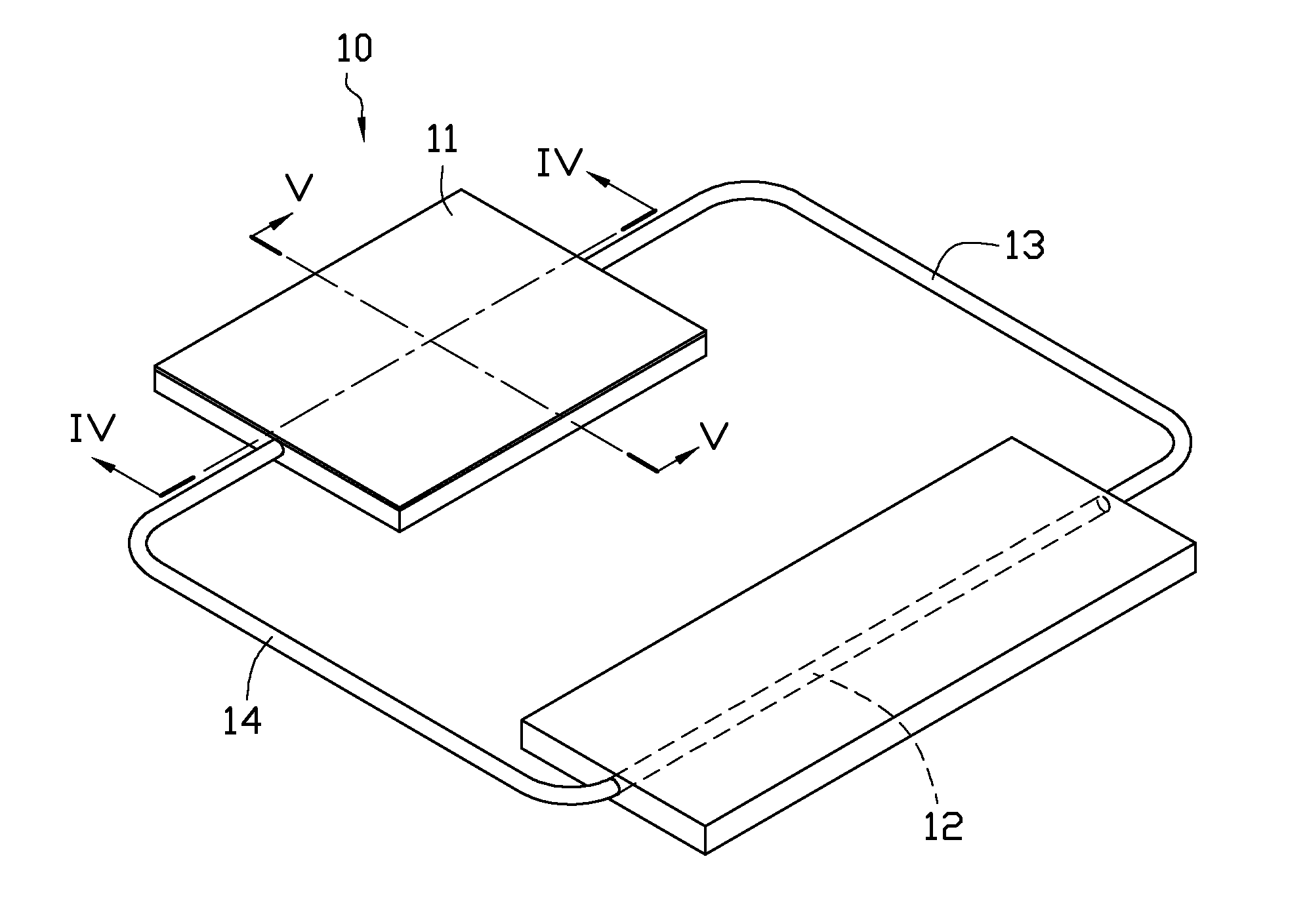
[0017]Referring to FIGS. 1 and 2, a loop heat pipe 10 according to the present disclosure is shown. The loop heat pipe 10 includes an evaporator 11, a condenser 12, and a vapor line 13 and a liquid line 14 connecting the evaporator 11 and the condenser 12 to form a closed loop. A predetermined quantity of bi-phase working medium (not shown) is filled in the closed loop. The working medium is a liquid which has a relatively low boiling point, such as water, methanol, or alcohol. Thus the working medium can easily evaporate when it absorbs heat transferred to the evaporator 11 from an external heat-generating object, and easily condense to liquid when it dissipates heat to the ambient environment at the condenser 12.

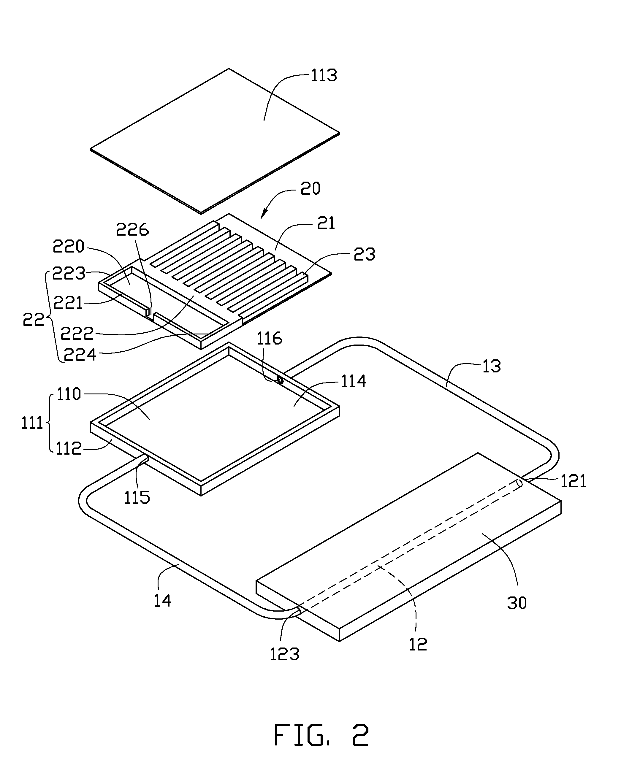
[0018]Referring also to FIG. 3, the evaporator 11 is rectangular and has a flat shape, and includes a base 111, a wick structure 20 received in the base 111, and a cover plate 113 covering the base 111. The base 111 includes a rectangular bottom plate 110, and a side plate...

second embodiment

[0026]FIG. 6 shows a wick structure 20a of a loop heat pipe according to a The wick structure 20a differs from the previous embodiment only in that the wick structure 20a further includes a top wall 24 located on the tops of the guide walls 23. When the wick structure 20a is received in the evaporator 11, the top wall 24 and the bottom wall 21 respectively contact the bottom surface of the cover plate 113 and the top surface of the bottom plate 110. In this embodiment, a portion of the top wall 24, which is right above the guide walls 23, can also function as a heating-absorbing area to make thermal contact with an electronic component and absorb heat generated therefrom.

[0027]FIG. 7 shows a wick structure 20b of a loop heat pipe according to a third embodiment. The wick structure 20b differs from the second embodiment mainly in that a transverse cross-section of each of guide channels 227b is circular. Another difference between the loop heat pipe of the third embodiment and the l...


PUM


Abstract

An exemplary loop heat pipe includes an evaporator, a condenser, a vapor line and a liquid line each connecting the evaporator with the condenser to form a closed loop. A working medium is contained in the closed loop. A wick structure is received in the evaporator, and includes a bottom wall contacting the bottom plate, a support wall extending up from the bottom wall and contacting the cover plate, and guide walls extending out laterally from the support wall. The support wall separates an interior of the evaporator into a liquid chamber adjacent to the liquid line and a vapor chamber adjacent to the vapor line. The guide walls are located in the vapor chamber. Guide channels are defined between the guide walls for guiding the working medium in a vapor state to flow from the vapor chamber through the vapor line to the condenser.

Description

BACKGROUND[0001]1. Technical Field[0002]The disclosure generally relates to heat transfer apparatuses, and particularly to a loop heat pipe with a high heat transfer efficiency.[0003]2. Description of Related Art[0004]Loop heat pipes are widely used in various fields for heat dissipation purposes due to their excellent heat transfer performance A commonly used loop heat pipe includes an evaporator thermally attached to a heat-generating electronic component, a condenser, and a vapor line and a liquid line respectively interconnected between the evaporator and the condenser. A predetermined quantity of bi-phase working medium is contained in the loop heat pipe. A wick structure, lining an inner surface of the evaporator, draws condensed working medium back to the evaporator after the working medium in vaporized form has condensed at the condenser.[0005]In operation of the loop heat pipe, the working medium conveys heat from the evaporator to the condenser. More specifically, the work...

Claims


Application Information

Patent Timeline
IPC IPC(8): F28D15/04
CPCF28D15/0266F28D15/043H01L23/427H01L2924/0002H01L2924/00
Inventor WANG, DE-YUXU, CHAOHU, JIANG-JUN
Owner FU ZHUN PRECISION IND SHENZHEN
Why Eureka
Try Eureka