Apparatus and method for determining refrigerant charge level

a technology of refrigerant charge and apparatus, applied in the direction of domestic cooling apparatus, heat measurement, instruments, etc., can solve the problems of time-consuming and costly procedures, system overcharge or undercharge, and inability to provide quantitative information, etc., to achieve low-cost non-invasive and low-cost effects

Active Publication Date: 2009-12-15
PURDUE RES FOUND INC
View PDF8 Cites 40 Cited by
  • Summary
  • Abstract
  • Description
  • Claims
  • Application Information

AI Technical Summary

Benefits of technology

[0010]From the above, it can be appreciated that the present invention provides a method and apparatus capable of determining the level of refrigerant charge using low-cost non-invasive measurements obtained while the system is operating. In particular, the method and apparatus are able to quantitatively determine refrigerant charge levels based on readily available manufacturers' data, limited or no training data, and surface-mounted temperature sensors that do not disturb the operation of the system or risk leakage of refrigerant. As such, the present invention can be implemented at relatively low cost. Furthermore, the performance of the method and apparatus is not compromised by the existence of other system faults.

Problems solved by technology

However, this technique does not provide quantitative information on charge level, and therefore can lead to a system being overcharged or undercharged.
Current common practices for accurately determining the charge level in a vapor-compression cycle system require evacuating the system and weighing the removed refrigerant, a very time-consuming and costly procedure that involves removing existing mineral oil, recovering existing refrigerant, evacuating the system using a deep vacuum, and refilling the system with proper amounts of mineral oil and refrigerant.
Drawbacks to such an approach include the requirement to operate the system over a range of different refrigerant charges and ambient conditions, necessitating a considerable amount of labor to alter the ambient conditions and adjust the refrigerant charge, the latter of which incurs the risk of refrigerant leakage.
Furthermore, pressure sensors are relatively expensive and their installation requires fittings that can further increase the probability of refrigerant leakage.
The algorithm proposed by Temple et al. also is not well suited to monitor refrigerant charge level if faults other than incorrect refrigerant charge are present.

Method used


Image

  • Apparatus and method for determining refrigerant charge level
  • Apparatus and method for determining refrigerant charge level
  • Apparatus and method for determining refrigerant charge level

Examples


Embodiment Construction

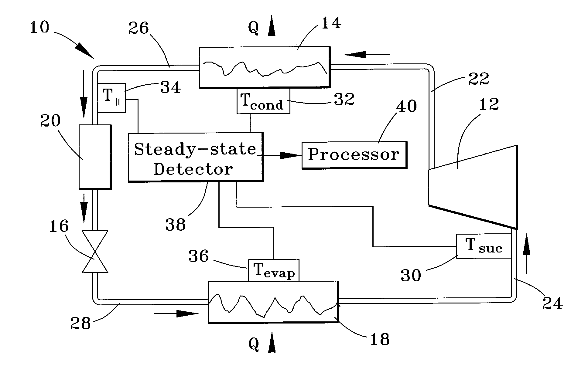
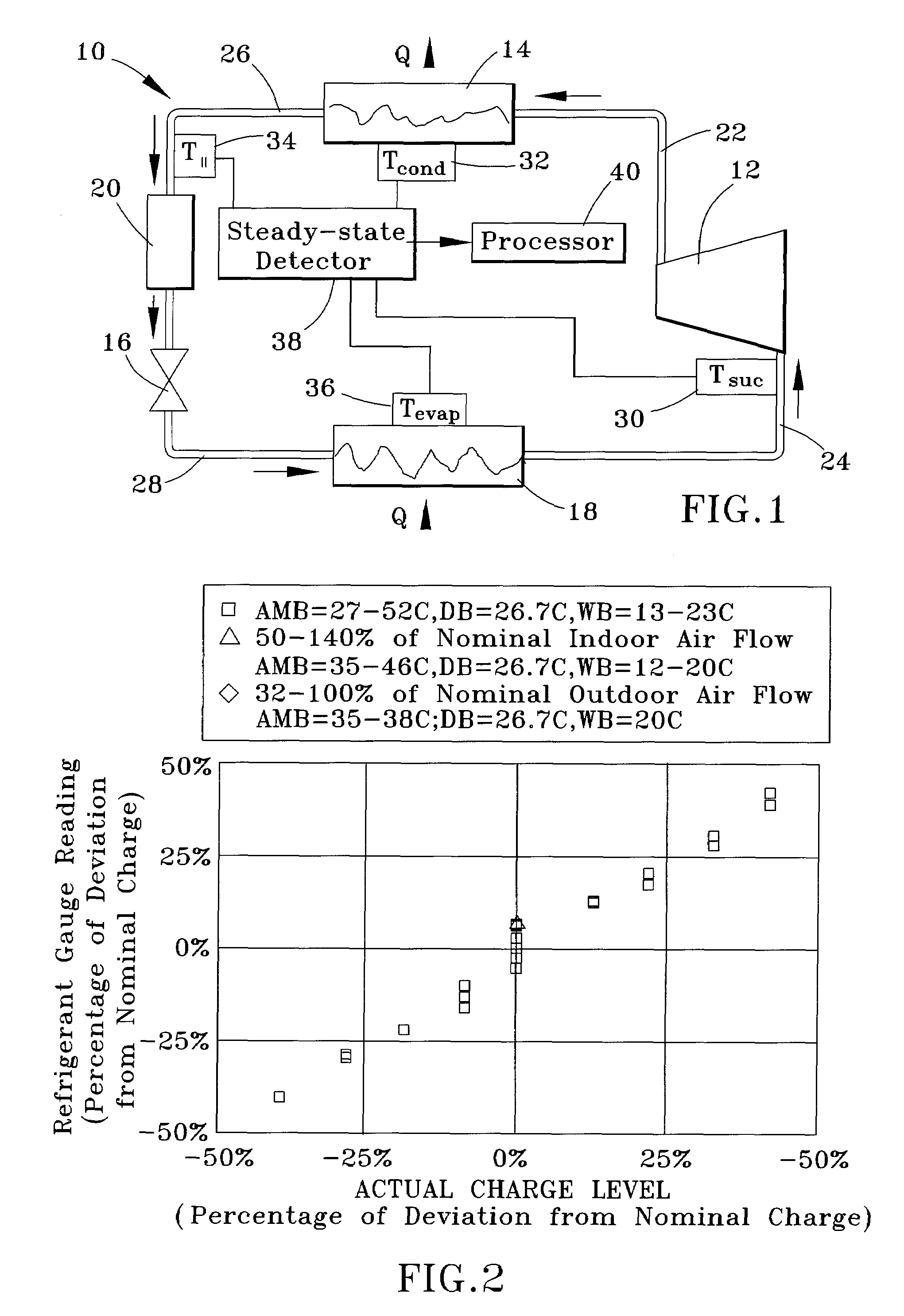
[0015]A typical vapor-compression refrigeration cycle system 10 is illustrated in FIG. 1. The system 10 includes a compressor 12, a condenser 14, an expansion device 16, and an evaporator 18. As is common, FIG. 1 also shows a filter / drier 20 installed in the system 10 between the expansion device 16 and evaporator 18. The various components of the system 10 can be fluidically connected with conduits, such as copper tubing or any other fluidic connections.

[0016]As known in the art, the compressor 12 increases pressure in the system 10 by compressing a refrigerant vapor. The conduit connecting the outlet of the compressor 12 to the condenser 14 is typically referred to as a discharge line 22, and thermodynamic states of the refrigerant within the discharge line 22, for example, pressure, temperature, enthalpy, etc., are referred to as, for example, discharge pressure, discharge temperature, discharge enthalpy, etc. The conduit connecting the inlet 26 of the compressor 12 to the evapor...


PUM

PropertyMeasurementUnit
temperatureaaaaaaaaaa
wet bulb temperatureaaaaaaaaaa

Abstract

A method and apparatus for non-invasively determining a charge level of a refrigerant in a vapor-compression cycle system. The method and apparatus monitor the system while the system is operated to ascertain that the system is operating at approximately steady-state. The superheat and the subcooling of the system are then determined at the suction line and at the liquid line, respectively, and the refrigerant charge level is calculated based on the determined subcooling, the determined superheat, and rated operating conditions of the system, including rated refrigerant charge level, rated liquid line subcooling, and rated suction line superheat.

Description

CROSS REFERENCE TO RELATED APPLICATIONS[0001]This application claims the benefit of U.S. Provisional Application No. 60 / 760,012, filed Jan. 18, 2006, the contents of which are incorporated herein by reference.BACKGROUND OF THE INVENTION[0002]The present invention generally relates to vapor-compression cycle equipment, and more particularly to determining the level of refrigerant charge using low-cost non-invasive measurements obtained while the system is operating.[0003]Vapor-compression cycle systems include air conditioners, heat pumps, chillers, refrigerators, coolers, etc. Proper refrigerant charge (the amount of refrigerant contained in the system) is essential for a vapor-compression cycle system to operate efficiently and safely. Charging charts are often employed to adjust an existing refrigerant level during the operation of vapor-compression cycle systems with refrigerant recovery. However, this technique does not provide quantitative information on charge level, and there...

Claims


Application Information

Patent Timeline
Patent Type & Authority Patents(United States)
IPC IPC(8): F25B45/00F25B49/00G01K13/00
CPCF25B49/005F25B2500/19F25B2700/04F25D2500/04F25B2700/2116F25B2700/21163F25B2700/2117F25B2700/21151
Inventor BRAUN, JAMES E.LI, HAORONG
Owner PURDUE RES FOUND INC
Why Eureka
Try Eureka