
Loop heat pipe and startup method for the same

a technology of loop heat pipe and startup method, which is applied in the direction of basic electric elements, semiconductor devices, lighting and heating apparatus, etc., can solve the problem of difficulty in securing an area for accommodating

Inactive Publication Date: 2012-05-31
FUJITSU LTD
View PDF1 Cites 36 Cited by
  • Summary
  • Abstract
  • Description
  • Claims
  • Application Information

AI Technical Summary

Benefits of technology

[0019]The object and advantages of the embodiments will be realized and attained by means of the elements and combinations particularly pointed out in the claims.
[0020]It is to be understood that both the foregoing general description and the following detailed description are exemplary and explanatory only and are not restrictive of the invention, as claimed.

Problems solved by technology

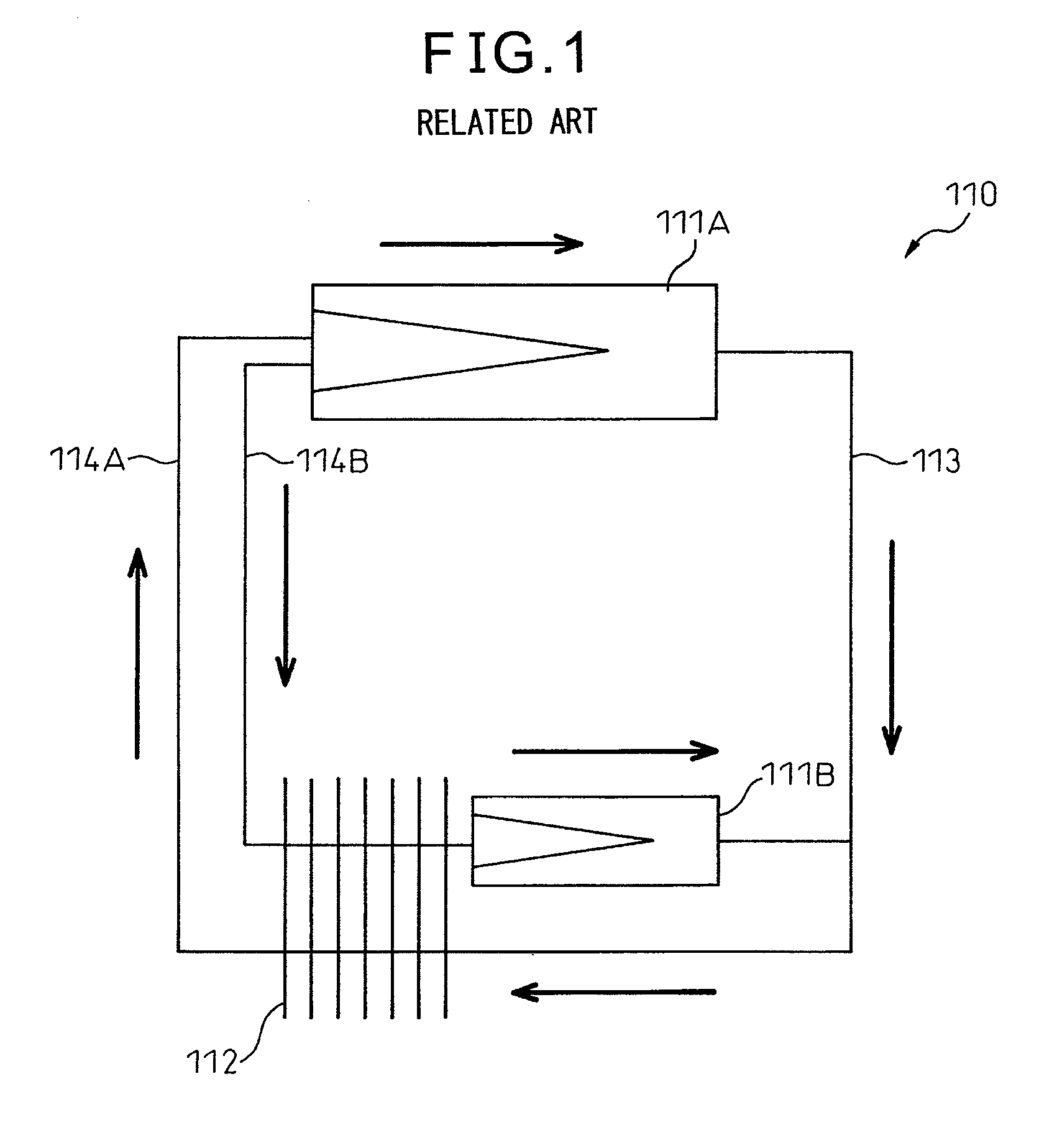
There are therefore cases in which it is difficult to secure an area for accommodating two loop heat pipes on the substrate.

Method used


Image

  • Loop heat pipe and startup method for the same
  • Loop heat pipe and startup method for the same
  • Loop heat pipe and startup method for the same

Examples


working examples

Working Example 1

[0159]First, a loop heat pipe of the structure depicted in FIG. 8 was fabricated. Then, the loop heat pipe was assembled into a blade server such as depicted in FIG. 3. The blade server was set with its substrate surface oriented perpendicularly to the plumbline direction so that the two evaporators were arranged in a horizontal plane. The heat load of the CPU A whose heat was to be transferred to the first evaporator was 0 W, and the heat load of the CPU B whose heat was to be transferred to the second evaporator was 60 W; the loop heat pipe thus fabricated was taken as Working Example 1.

working example 2

[0160]Working Example 2 was fabricated in the same manner as Working Example 1, except that the heat load of the CPU A whose heat was to be transferred to the first evaporator was 20 W, and the heat load of the CPU B whose heat was to be transferred to the second evaporator was 60 W.

working example 3

[0161]Working Example 3 was fabricated in the same manner as Working Example 1, except that the heat load of the CPU A whose heat was to be transferred to the first evaporator was 40 W, and the heat load of the CPU B whose heat was to be transferred to the second evaporator was 60 W.


PUM


Abstract

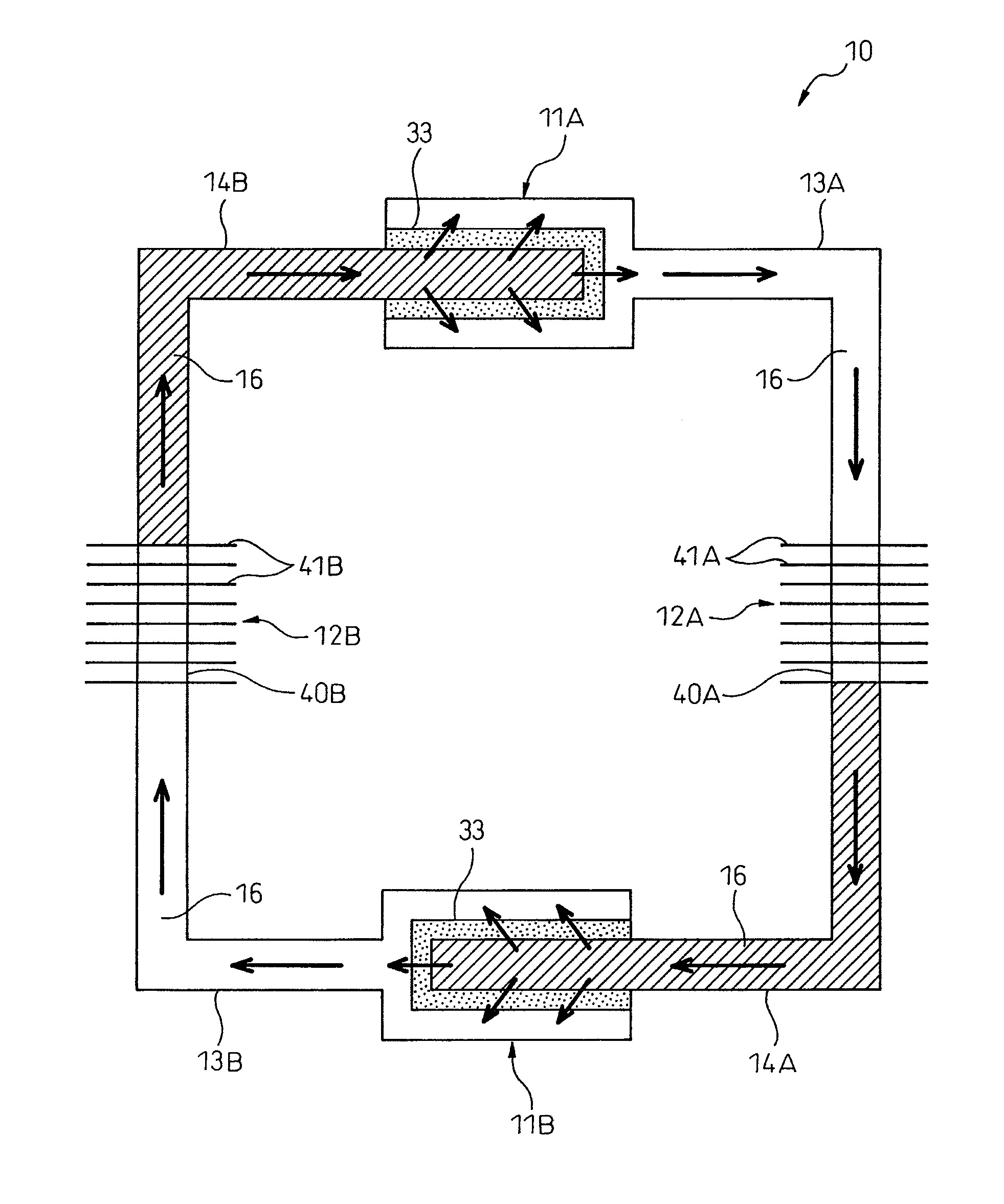
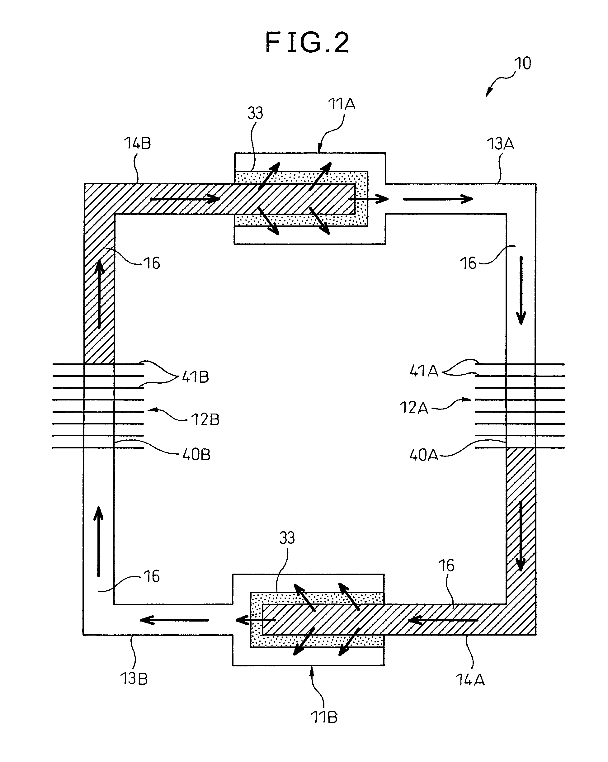
A loop heat pipe includes: a first evaporator and a second evaporator each of which vaporizes a liquid-phase working fluid and converts the liquid-phase working fluid to a vapor-phase working fluid; a first condenser and a second condenser each of which condenses the vapor-phase working fluid and converts the vapor-phase working fluid back to the liquid-phase working fluid; a first vapor line through which the working fluid converted to the vapor phase is transported to the first condenser; a first liquid line through which the working fluid converted to the liquid phase is transported to the second evaporator; a second vapor line through which the working fluid converted to the vapor phase is transported to the second condenser; and a second liquid line through which the working fluid converted to the liquid phase is transported to the first evaporator.

Description

CROSS-REFERENCE TO RELATED APPLICATIONS[0001]This application is based upon and claims the benefit of priority of the prior Japanese Patent Application No. 2009-164960, filed on Jul. 13, 2009, and International Patent Application PCT / JP2010 / 056093, filed on Apr. 2, 2010, the entire contents of which are incorporated herein by reference.TECHNICAL FIELD[0002]The present invention is related to a loop heat pipe and a startup method for the same.BACKGROUND ART[0003]Heat pipes are used for cooling electronic devices. A heat pipe is a heat transfer device that transports heat by utilizing the phase change of the working fluid sealed therein.[0004]In order to enhance the cooling capability for cooling electronic devices, a heat pipe known as a loop heat pile has been developed that can transport a larger heat load over a longer distance.[0005]The loop heat pipe includes an evaporator which receives heat from a heat source and vaporizes a liquid-phase working fluid, and a condenser which co...

Claims


Application Information

Patent Timeline
Patent Type & Authority Applications(United States)
IPC IPC(8): F28D15/02
CPCF28D15/0266F28D15/06F28F2250/06H01L23/427H01L2924/0002H05K7/20809H01L2924/00
Inventor AOKI, SHIGENORISHIOGA, TAKESHIUCHIDA, HIROKI
Owner FUJITSU LTD
Learn More