Piling apparatus having rotary drive

Inactive Publication Date: 2009-02-24
WHITSETT MICHAEL
View PDF13 Cites 31 Cited by
  • Summary
  • Abstract
  • Description
  • Claims
  • Application Information

AI Technical Summary

Benefits of technology

[0034]A second drive installation tool is bolted to the first. A second formed square sectional hollow form is placed over the drive tool and bolted. The hydraulic planetary drive unit is placed on top of the drive tool and the complete pile section is then screwed down into the soil until the top section reaches near ground level. This same process of installing drive tools and sectional hollow form units is repeated until the proper depth form has been reached (i.e. to satisfy the pile load requirements). As the complete pile unit is screwed down into the earth, the soil displacer ribs will push the soil outward away from the hollow pipe sec

Problems solved by technology

High capacity pile driving equipment is large and cumbersome to operate in confined areas.
Conventional pile driving equipment can cause stress and fatigue on adjacent structures from weight and vibration.
A problem with this technique is that in weak soils the hole tends to collapse.
Therefore, expensive shoring is required.
If the hole

Method used


Image

  • Piling apparatus having rotary drive
  • Piling apparatus having rotary drive
  • Piling apparatus having rotary drive

Examples


Example

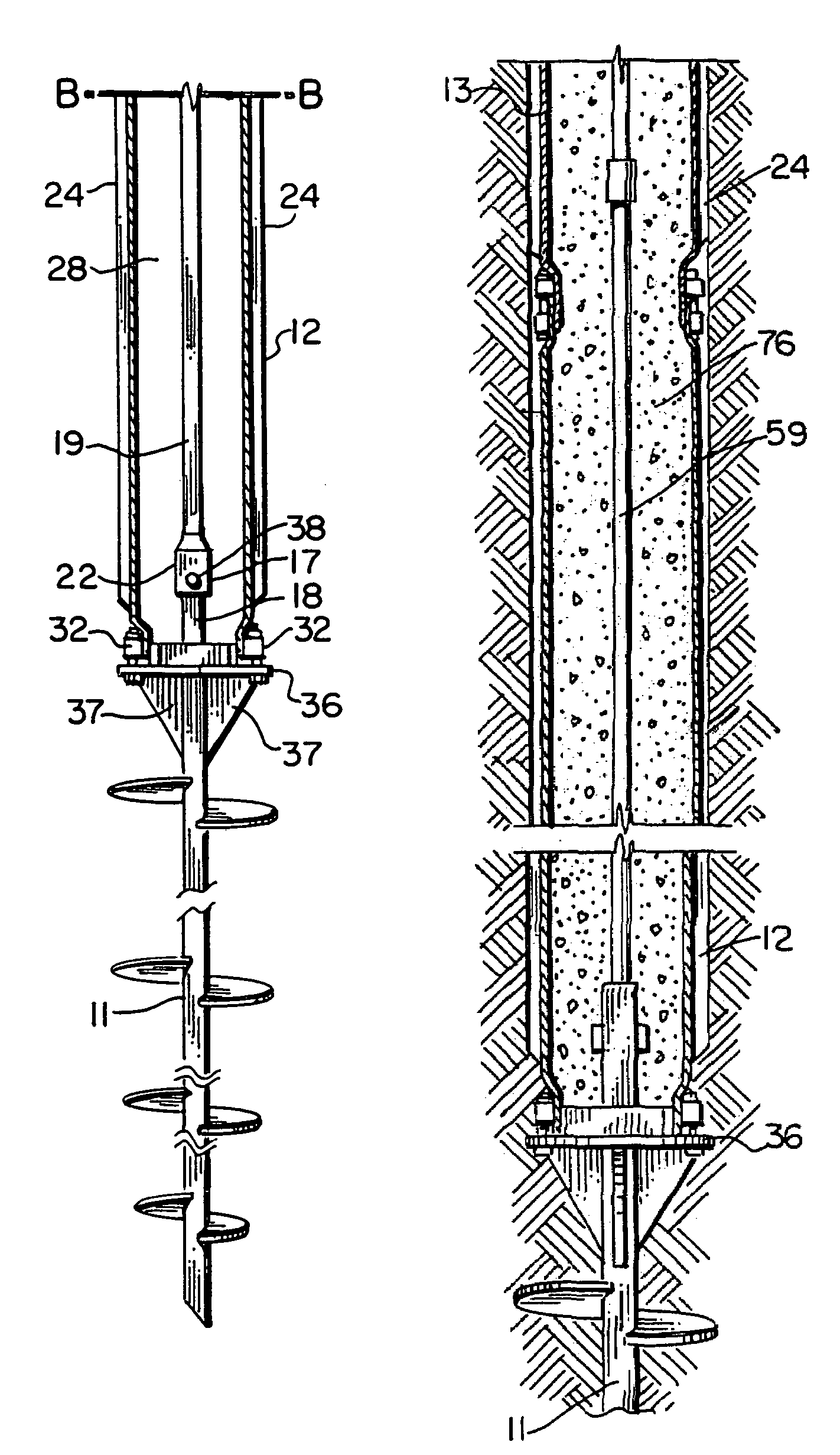
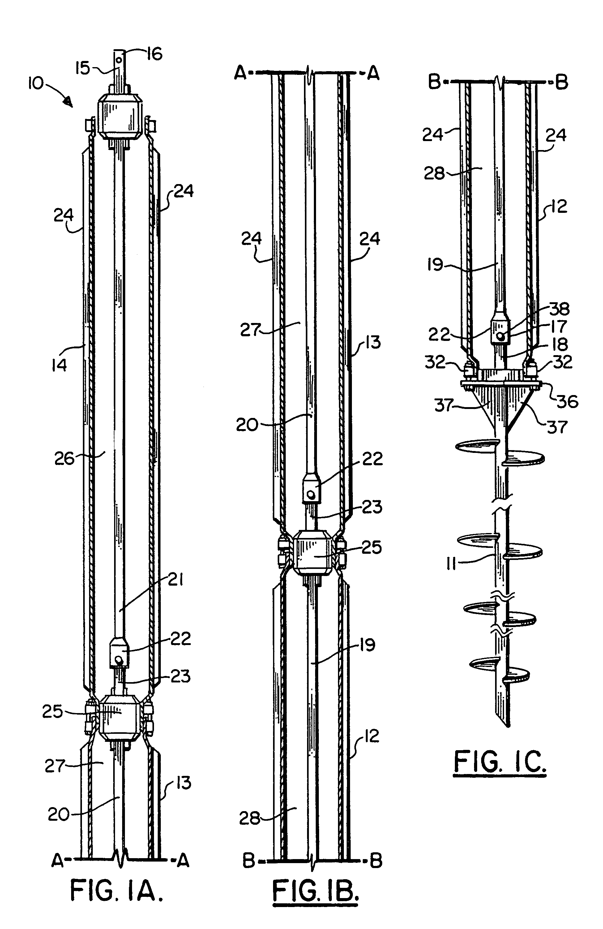
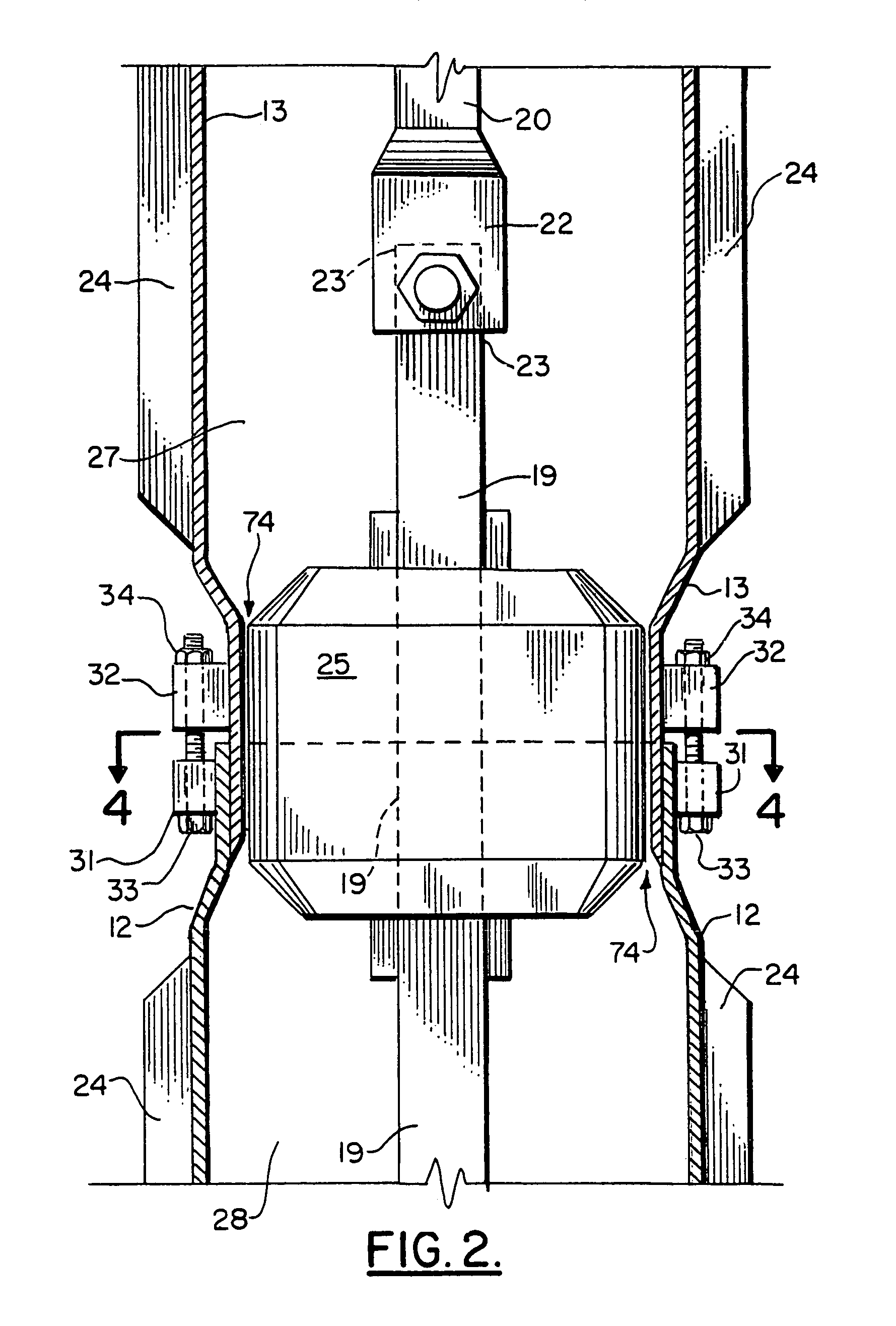
[0077]In FIGS. 1A-1C, the preferred embodiment of the apparatus of the present invention is designated generally by the numeral 10. It should be understood that in order to fit an entire elevation, sectional view of the apparatus 10 of the present invention on a single page, matchline type drawings are used wherein FIG. 1A fits to the top of FIG. 1B along matchlines A-A. Similarly, FIG. 1C fits to the bottom of FIG. 1B at matchlines. In situ pile apparatus 10 includes generally a lowermost, first section in the form of helical anchor 11, a second section 12 which is a hollow pile form section, a third section 13 and a fourth section 14. The third and fourth sections 13, 14 are also hollow pile form sections. Each section 12, 13, 14 has an internal bore. Section 12 has bore 28. Section 13 has bore 27. Section 14 has bore 26.

[0078]In the preferred embodiment, the sections 12, 13, 14 are preferably interchangeable pile sections. An internal drive member 15 extends through a hollow bore...


PUM


Abstract

An in-situ pile apparatus 10 includes a helical anchor to which a plurality of elongated generally cylindrically shaped sections can be added. Each of the sections has a specially shaped end portion for connecting to another section. An internal drive is positioned in sections inside the bore of each of the connectable pile sections. The internal drive includes enlarged sections that fit at the joint between pile sections. In one embodiment, the internal drive can be removed to leave a rod behind that defines reinforcement for an added material such as concrete. The rod also allows for a tension rod connection from the anchor tip to an upper portion attachment point.

Description

CROSS-REFERENCE TO RELATED APPLICATIONS[0001]Priority of U.S. Provisional Patent Application Ser. No. 60 / 248,349, filed Nov. 14, 2000, incorporated herein by reference, is hereby claimed. This is a continuation in part of Ser. No. 09 / 993,321 filed Nov. 14, 2001, now U.S. Pat. No. 6,814,525, the priority of which is claimed and the full disclosure of which is incorporated herein by reference.STATEMENT REGARDING FEDERALLY SPONSORED RESEARCH OR DEVELOPMENT[0002]Not applicableREFERENCE TO A “MICROFICHE APPENDIX”[0003]Not applicableBACKGROUND OF THE INVENTION[0004]1. Field of the Invention[0005]The present invention relates to composite piling and more particularly to a piling apparatus that includes a helical anchor lower end portion to which a plurality of connectable sections can be added, each section having a hollow interior through which a drive member can pass, and each section being joined to another section at a joint that has a specially shaped fitting to be engaged by an enlar...

Claims


Application Information

Patent Timeline
IPC IPC(8): E02D7/30E02D5/38
CPCE02D5/38E02D5/52E02D5/54E02D5/72E02D7/28
Inventor WHITSETT, MICHAEL
Owner WHITSETT MICHAEL
Why Eureka
Try Eureka