Unlock instant, AI-driven research and patent intelligence for your innovation.

Delay-locked loop (DLL) system for determining forward clock path delay

a delay-locked loop and forward clock technology, applied in the field of delay-locked loops for determining forward clock path delay, can solve the problems of internal components not being well synchronized with the external clock signal, affecting the performance of internal components at relatively high speeds, and causing time delay of clock signals

Active Publication Date: 2009-02-24
MICRON TECH INC
View PDF3 Cites 15 Cited by
  • Summary
  • Abstract
  • Description
  • Claims
  • Application Information

AI Technical Summary

Problems solved by technology

When an external clock signal is propagated to internal components, a time delay of the clock signal occurs.
The internal components may not be well synchronized with the external clock signal, which can affect the performance of the internal components at relatively high speeds.
Thus, the components in an electronic device may not be relatively well synchronized even though they are clocked by the same external or reference clock signal.
In addition, variations in operating conditions such as operating temperature and external power supply may also vary propagation delay, resulting in changes to clock delay.

Method used


Image

  • Delay-locked loop (DLL) system for determining forward clock path delay
  • Delay-locked loop (DLL) system for determining forward clock path delay
  • Delay-locked loop (DLL) system for determining forward clock path delay

Examples


Embodiment Construction

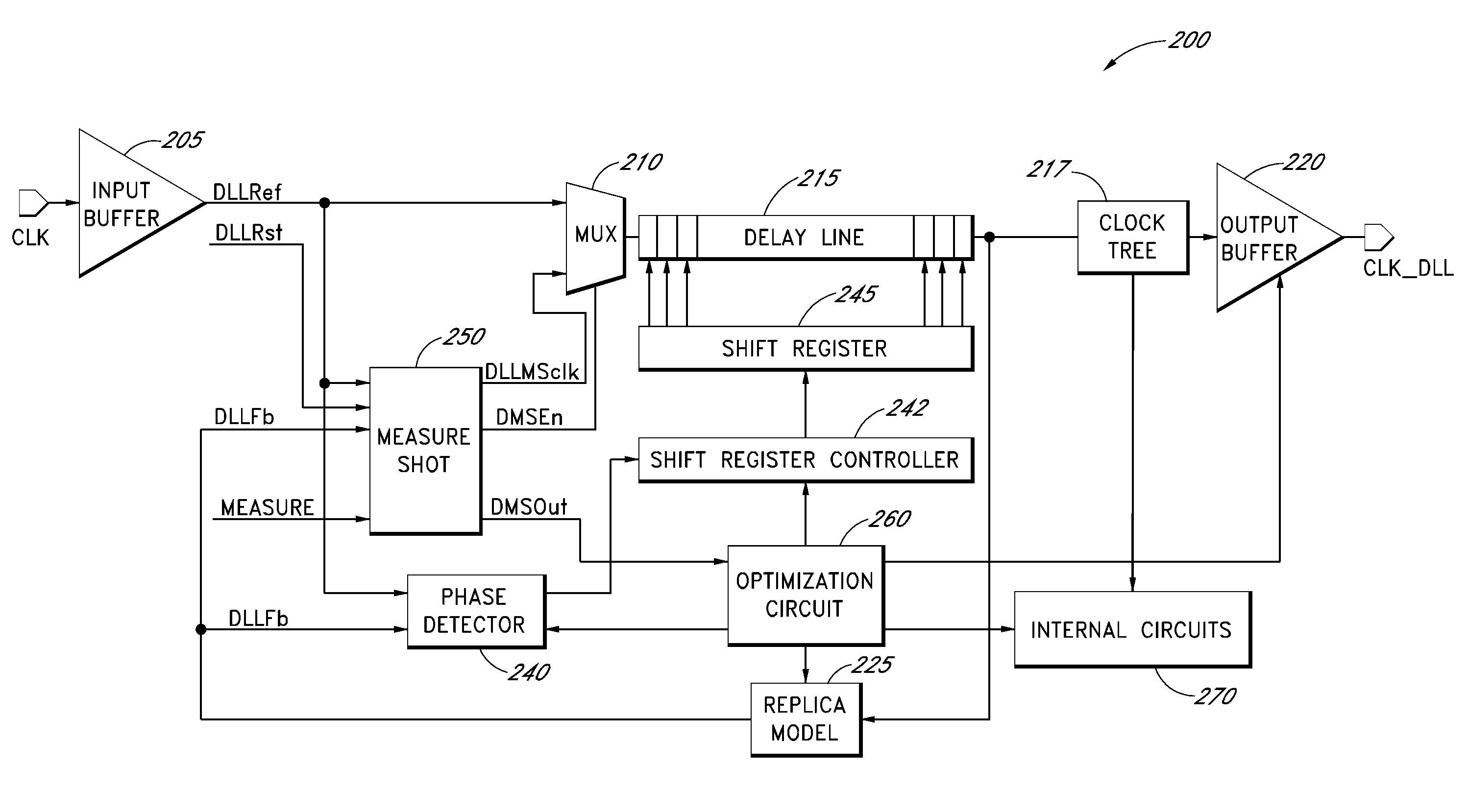
[0024]High-speed electronic devices often demand a minimal delay along the forward clock path so as to provide relatively low latency, relatively good timing margin, and relatively fast data throughput. Optimizing a delay along the delay line of a DLL is a good design practice. However, the delay is susceptible to changes in various factors such as external clock frequency, process model, process, voltage, and temperature variations (PVT), external power supply, internal power bussing voltage, and the like. Therefore, there is a need to calibrate a DLL configuration in response to such changes.

[0025]During normal operation, an external clock signal is provided to a DLL system. However, when the DLL system is being calibrated, the external clock signal is stopped to clear the DLL loop. A calibration signal is applied again to the DLL system. Delays along the DLL loop is determined by detecting a single (or first) edge of the clock signal when the calibration signal has turned around ...


PUM


Abstract

A delayed locked loop (DLL) system and method for determining a forward clock path delay are disclosed. One embodiment of the DLL system includes a delay line having a plurality of delay stages. The DLL system also includes a measure shot device configured to determine a forward clock path delay of the DLL system. The measure shot device is configured to provide a calibration sequence into the DLL loop and to detect the calibration sequence after the calibration sequence has passed through the DLL loop. The measure shot device is further configured to count the number of clocks for a period of time between providing and detecting the calibration sequence. The number of clocks can be used to calibrate components of the DLL system.

Description

BACKGROUND OF THE INVENTION[0001]1. Field of the Invention[0002]Embodiments of the invention relate to electronic devices, and more particularly, to electronic devices including a delay-locked loop (DLL).[0003]2. Description of the Related Art[0004]High speed electronic devices such as DRAM are often provided with external or reference clock signals for timing the operations of their internal components. When an external clock signal is propagated to internal components, a time delay of the clock signal occurs. The internal components may not be well synchronized with the external clock signal, which can affect the performance of the internal components at relatively high speeds.[0005]In addition, various components in an electronic device can have different manufacturing parameters. Thus, the components in an electronic device may not be relatively well synchronized even though they are clocked by the same external or reference clock signal. In addition, variations in operating con...

Claims


Application Information

Patent Timeline
Patent Type & Authority Patents(United States)
IPC IPC(8): H03L7/06
CPCH03L7/0805H03L7/0814H03L7/0816
Inventor MA, YANTAOWRIGHT, JEFFREY P
Owner MICRON TECH INC
Features
  • R&D
  • Intellectual Property
  • Life Sciences
  • Materials
  • Tech Scout
  • Unparalleled Data Quality
  • Higher Quality Content
  • 60% Fewer Hallucinations
Learn More