Retention clip

a technology of retention clip and clip, which is applied in the direction of threaded fasteners, snap fasteners, screwed fasteners, etc., can solve the problems of high insertion force used to install clips, difficult positioning of particular clips into holes, and use of separate tools, etc., and achieves the effect of low insertion for

Inactive Publication Date: 2009-03-03
ILLINOIS TOOL WORKS INC
View PDF13 Cites 27 Cited by
  • Summary
  • Abstract
  • Description
  • Claims
  • Application Information

AI Technical Summary

Benefits of technology

[0010]Optionally, the retaining tabs may be a plurality of planar, flat tabs evenly spaced about the main portion. The flat, board-like planar tabs allow for a lower insertion force as compared to the more robust louvered tabs.

Problems solved by technology

As such, positioning a particular clip into a hole may not be easy.
Thus, a high insertion force is used to install the clip into the hole formed through the panel.
The use of a separate tool typically adds time, cost and effort to the manufacturing process.

Method used


Image

  • Retention clip
  • Retention clip
  • Retention clip

Examples


Embodiment Construction

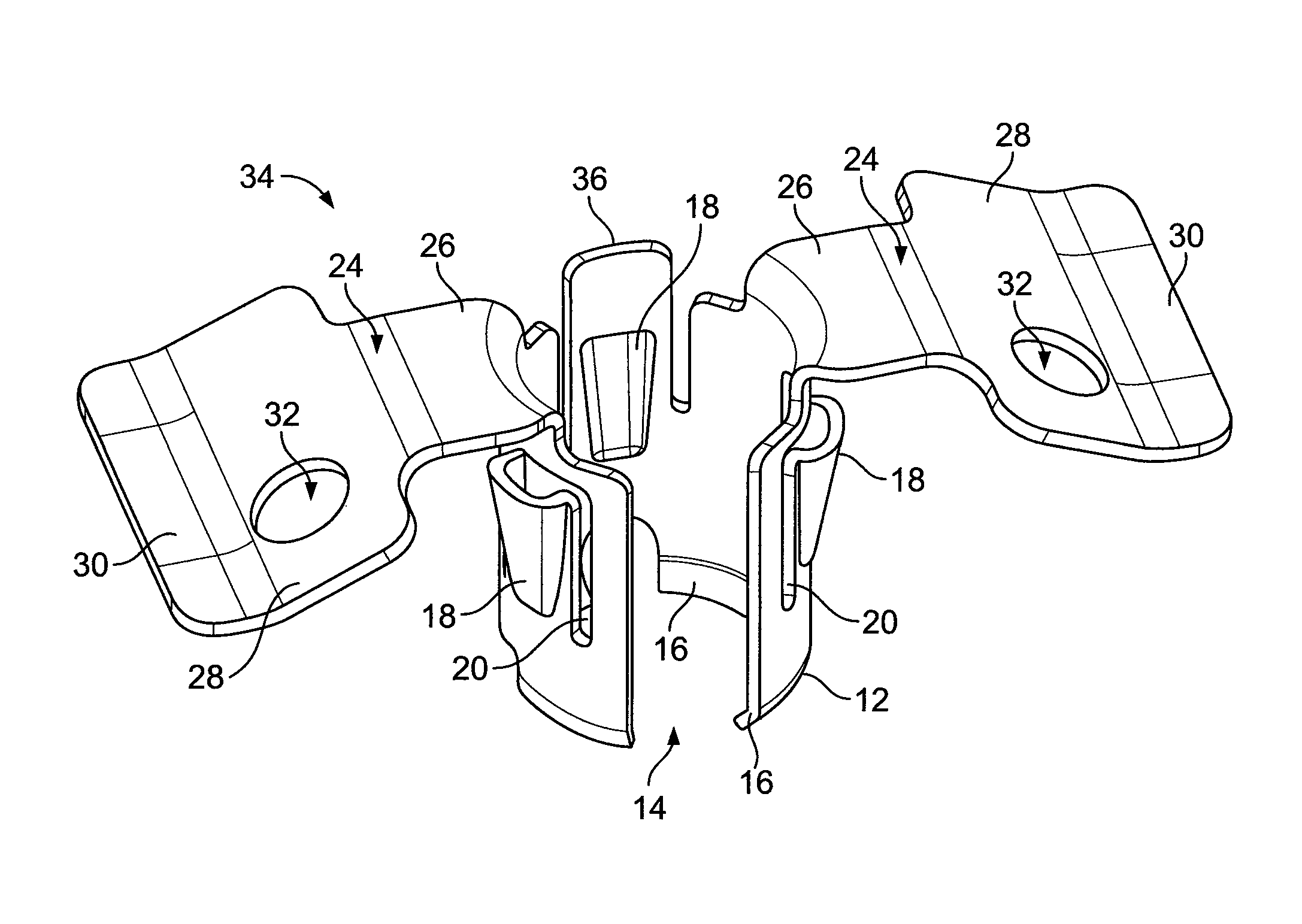
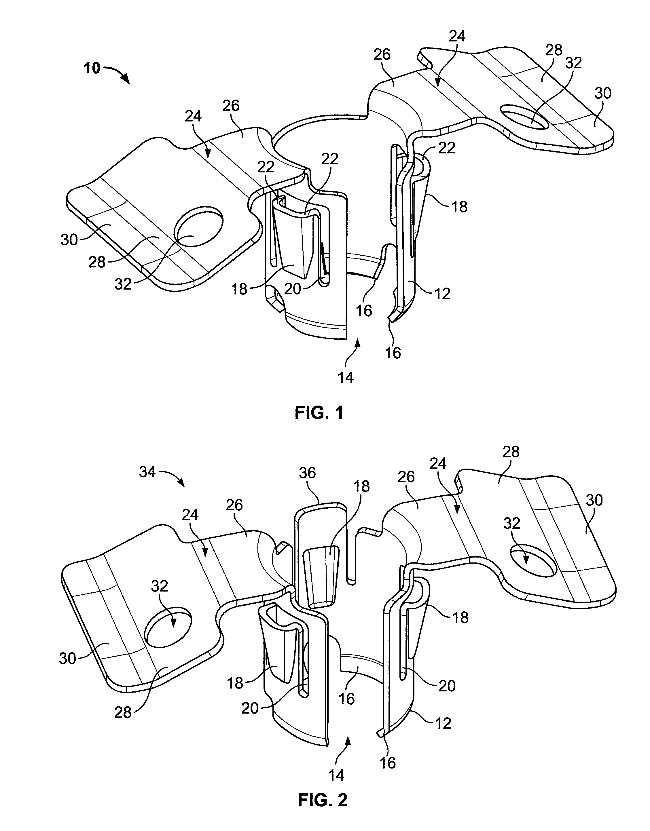
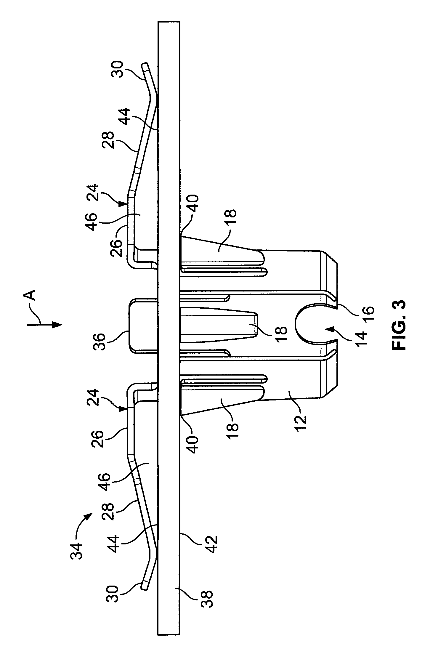
[0020]FIG. 1 illustrates an isometric view of a retention clip 10 according to an embodiment of the present invention. The retention clip 10 includes a generally cylindrical main portion, such as a main body or walls 12 having an opening 14 formed therein or therebetween. The shape of the main body 12 corresponds to the shape of a circular opening formed in a panel. Thus, the main body 12 is configured to easily pass into the opening. During insertion into a hole, the main body 12 may inwardly flex by way of the opening 14. That is, as the main body 12 passes into a hole, the edges defining the hole may squeeze the main body 12 through the space defined by the opening 14. In general, the opening 14 permits the retention clip 10 to inwardly deflect to facilitate insertion into, and removal from, a hole formed in a panel.

[0021]Lower or leading ends 16 of the main body 12 are inwardly canted, curved or the like. For example, the leading ends 16 may be radially canted, bent or curved to...


PUM


Abstract

A retention clip includes a generally cylindrical main portion having a leading end configured to pass into a hole of a panel, at least one retaining tab extending from the main portion, and at least one spring member extending from the main portion. The at least one retaining tab and the at least one spring member are configured to compressively sandwich a portion of the panel therebetween.

Description

RELATED APPLICATIONS[0001]This application relates to and claims priority benefits from U.S. Provisional Patent Application No. 60 / 873,862 entitled “Retention Clip,” filed Dec. 8, 2006, which is hereby incorporated by reference in its entirety.FIELD OF THE INVENTION[0002]Embodiments of the present invention generally relate to a retention clip, and more particularly to a retention clip having lateral spring-biased flaps or wings.BACKGROUND OF THE INVENTION[0003]Fastening clips are used in various applications. For example, fastening clips may be secured to a piece of sheet metal within an automobile. Another component, such as an airbag system, may then be secured to the sheet metal by way of the fastening clips.[0004]Typically, a tool is used to install the fastening clips to a piece of sheet metal. Indeed, various clips are secured to the piece of sheet metal through separate fasteners, such as screws or bolts, that threadably pass through portions of the clips. Further, the shape...

Claims


Application Information

Patent Timeline
Patent Type & Authority Patents(United States)
IPC IPC(8): F16B5/06
CPCF16B5/0621F16B19/004F16B21/08F16B21/076Y10T24/307Y10T24/304
Inventor KOSIDLO, JOHN M.CARRIER, JAMES B.GIMMY, KENT S.
Owner ILLINOIS TOOL WORKS INC
Why Eureka
Try Eureka