Tool extractable contacts for electrical connectors

a technology for extracting contacts and electrical connectors, applied in the field of connector systems, can solve problems such as failure of the device into which the connector is incorporated, inconsistent retention of pin and socket contacts, and reduced performance, and achieve the effect of effectively engaging the extraction tool

Active Publication Date: 2009-03-03
TYCO ELECTRONICS LOGISTICS AG (CH)
View PDF6 Cites 17 Cited by
  • Summary
  • Abstract
  • Description
  • Claims
  • Application Information

AI Technical Summary

Benefits of technology

[0008]In yet another aspect of this invention, a method for extracting an electrical contact from the housing portion of a connector assembly is provided. This method includes the steps of: inserting at least one specially modified contact, which may be either a pin contact or socket contact, into a housing component; and extracting the contact from the housing component with an extraction tool specifically designed to work with the contact. The contact typically includes a wire retaining portion and a mating portion formed integrally with a body portion. The body portion of the pin connector further includes at least one and typically two outwardly biased latches and each of these latches is adapted to effectively engage the extraction tool when the extraction tool is inserted into the housing. Each of the latches is typically formed from the same material as the body portion of the connector pin and is integral therewith and further includes an internal biasing member and an external engagement member formed at the end of the biasing member for frictionally engaging the extraction tool. The extraction tool simultaneously engages each of the latches and the application of sufficient force to the tool will extract the pin.

Problems solved by technology

For example, when in use, the pin and socket contacts may experience inconsistent retention within the housing portions of the connector system.
Inconsistent retention within the housing may lead to partial or total failure of the connector and consequently to diminished performance or even failure of the device into which the connector is incorporated.

Method used


Image

  • Tool extractable contacts for electrical connectors
  • Tool extractable contacts for electrical connectors
  • Tool extractable contacts for electrical connectors

Examples


Embodiment Construction

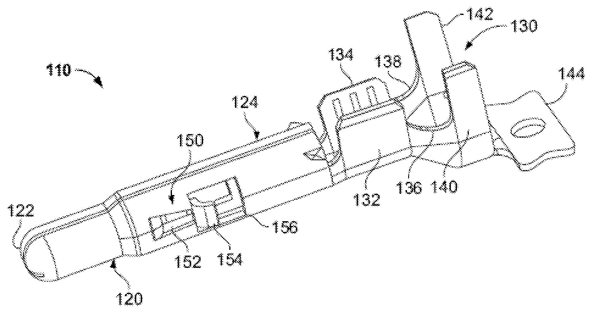
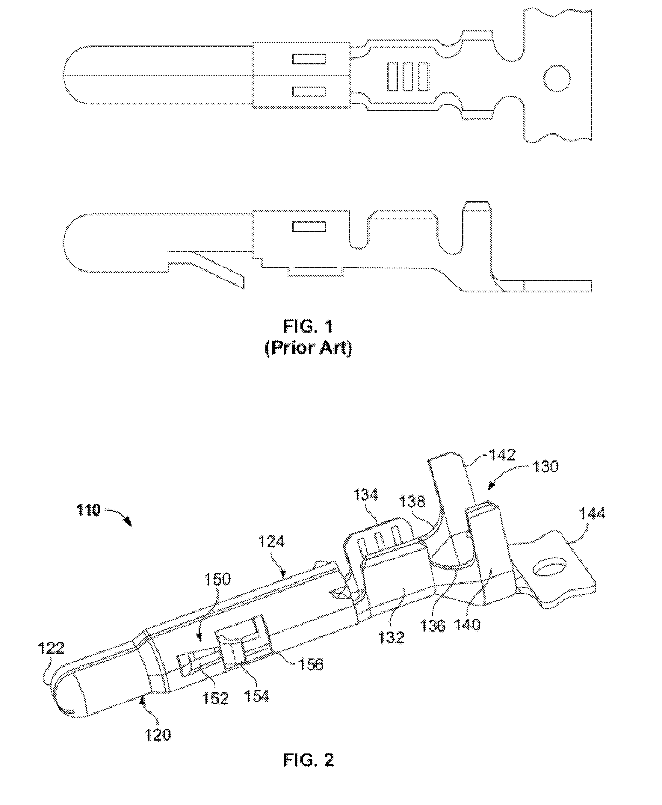
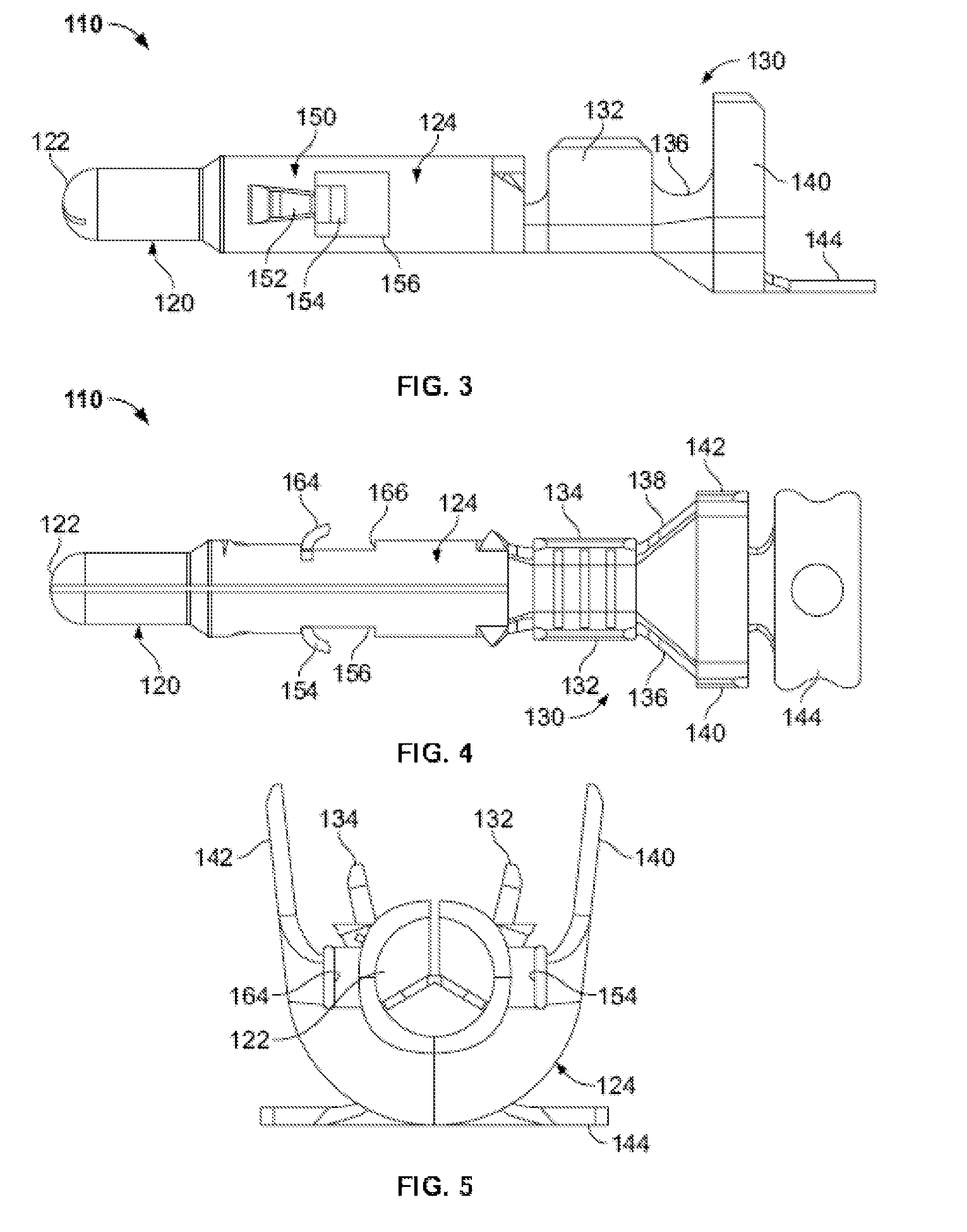
[0022]Exemplary embodiments of the present invention are now described with reference to the Figures. Reference numerals are used throughout the detailed description to refer to the various elements and structures. In other instances, well-known structures and devices are shown in block diagram form for purposes of simplifying the description. Although the following detailed description contains many specifics for the purposes of illustration, anyone of ordinary skill in the art will appreciate that many variations and alterations to the following details are within the scope of the invention. Accordingly, the following embodiments of the invention are set forth without any loss of generality to, and without imposing limitations upon, the claimed invention.

[0023]The present invention relates to a connector system that includes connector housing components and pin and socket contacts that are mounted within the housing components. A first general embodiment of this invention provides...


PUM

PropertyMeasurementUnit
lengthaaaaaaaaaa
electrically conductiveaaaaaaaaaa
anglesaaaaaaaaaa

Abstract

A connector system for use with electronics is provided. This system includes at least one electrical contact that further includes a wire retaining portion and an elongated body portion. The body portion of the contact further includes at least one outwardly biased latch that is adapted to engage both a contact cavity formed within a connector housing component and an extraction tool designed to remove the contact from the housing component, if necessary. The latch is formed from the same material as the body portion of the contact and further includes an internal biasing member and an external engagement member formed at the end of the biasing member for frictionally engaging the housing component and the extraction tool.

Description

CROSS-REFERENCE TO RELATED APPLICATIONS[0001]This patent application is a continuation-in-part of U.S. patent application Ser. No. 11 / 532,075 filed on Sep. 14, 2006 and entitled “ELECTRICAL CONTACT WITH WIRE TRAP”, the disclosure of which is incorporated by reference as if fully rewritten herein.BACKGROUND OF THE INVENTION[0002]The described invention relates in general to connector systems for use with electronic equipment, and more specifically to connector systems that utilize pin and socket type contacts (i.e., terminals) such as those typically found in MATE-N-LOK systems or comparable systems, wherein the pin and socket contacts are modified to be more easily extractable from connector housings using an extraction tool.[0003]“Molex connector” is a common term used for a two-piece “pin and socket” type interconnection that is frequently used for disk drive connectors and other devices. Pioneered by Molex Products Company, the two-piece design became an early standard in the ele...

Claims


Application Information

Patent Timeline
Patent Type & Authority Patents(United States)
IPC IPC(8): H01R11/20
CPCH01R4/185H01R13/432H01R13/64H01R13/585H01R13/04Y10T29/53209H01R13/6273
Inventor LAUERMANN, MARK E.DIEMER, DONALD A.BAUGHN, DONALD M.
Owner TYCO ELECTRONICS LOGISTICS AG (CH)
Why Eureka
Try Eureka