Shredder
a shredder and shredder body technology, applied in the field of shredders, can solve the problems of deteriorating shredding speed and reducing the life of the device, and achieve the effects of reducing the overload of an internal element, preventing abnormal operation and noise, and reducing the operation tim
- Summary
- Abstract
- Description
- Claims
- Application Information
AI Technical Summary
Benefits of technology
Problems solved by technology
Method used
Image
Examples
first embodiment
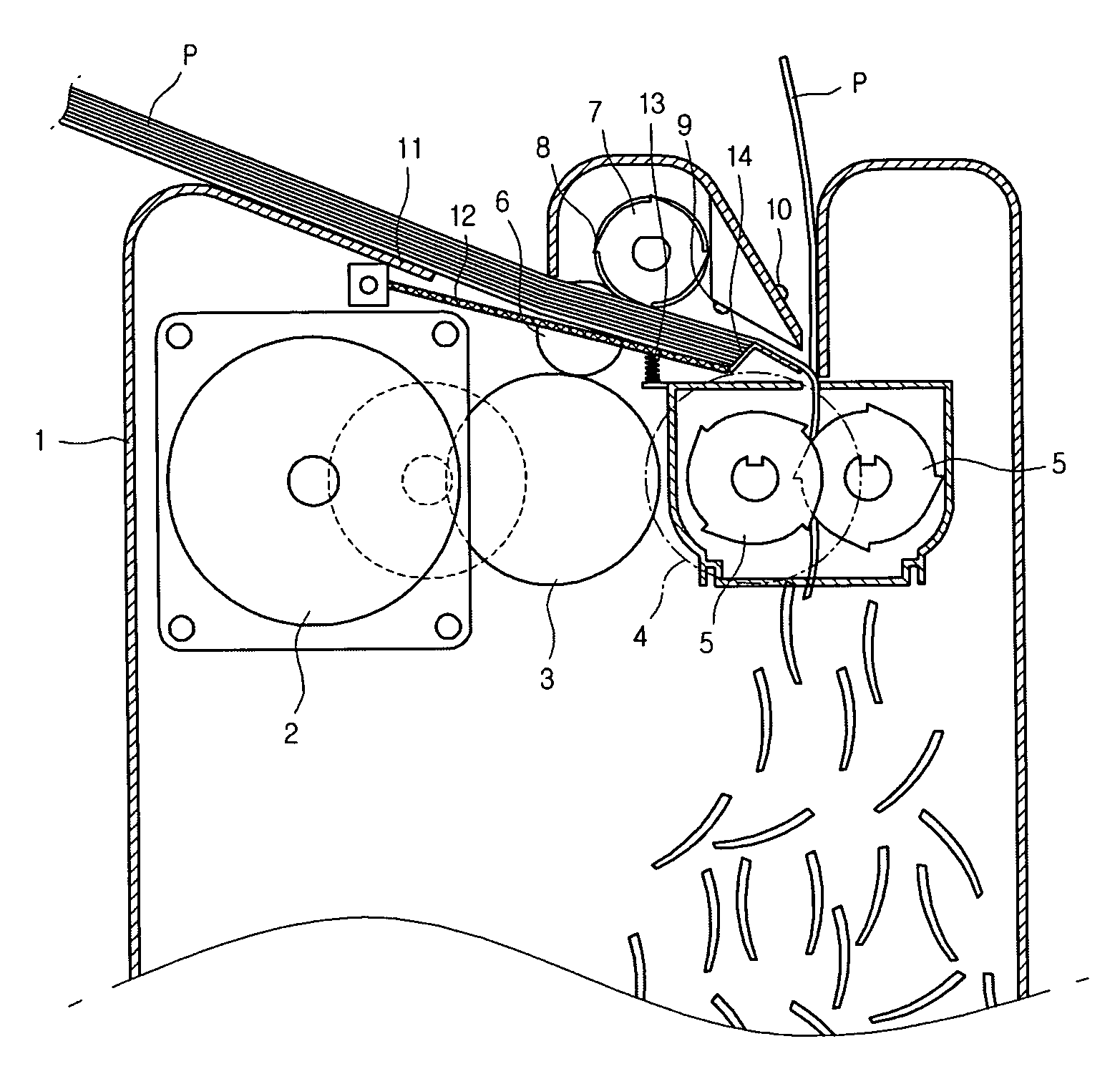
[0030]FIG. 1 is a cross-sectional view of a shredder according to a first embodiment of the present invention.
[0031]Referring to the embodiment illustrated in FIG. 1, the shredder according to the present invention can be characterized in that paper feeding can be controlled both manually and automatically.
[0032]Particularly, the shredder according to the present invention includes a case 1 forming an exterior of the shredder, a driving motor 2 formed inside the case 1 and providing a driving force, a connection part 3 transmitting a driving force of the driving motor 2 to a proper place, a cutter side connection gear 4 connected to the connection part 3 and transmitting a driving force to a cutter 5, and a feed side connection gear 6 connected to the connection part 3 and transmitting a driving force to an automatic paper feeding roller 7.
[0033]Particularly, an automatic feed side includes a paper feeding tray 11 on which a plurality of paper sheets are placed, a pressing part 12 p...
second embodiment
[0046]The second embodiment of the present invention is identical to the first embodiment except for the shape of the automatic paper feeding roller. Therefore, the same reference numbers will be used throughout the drawing to refer to the same or like parts as those in the first embodiment.
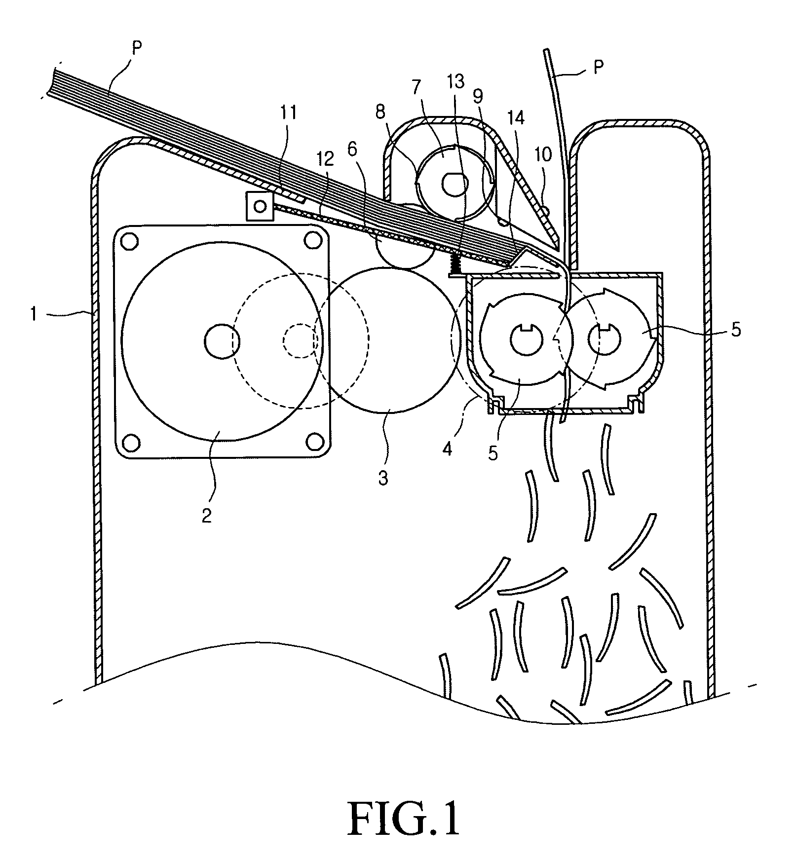
[0047]FIG. 2 is a front view of an automatic paper feeding roller according to the second embodiment of the present invention.
[0048]Referring to FIG. 2, in the present embodiment, provided are a plurality of automatic paper feeding rollers 7 for supplying paper sheets by certain amounts, a supply protrusion 8 formed near a central portion of each automatic paper feeding roller 7, and a roller shaft 15 for rotating the automatic paper feeding roller 7 at a constant speed. Although not shown, it is apparent to those skilled in the art that a gear engaged with the input side connection gear 6 is fixed to at least one side of the roller shaft 15.
[0049]In this embodiment of the present invention, the ...
third embodiment
[0050]The third embodiment is identical to the first embodiment except for the automatic paper feeding roller for automatically supplying paper sheets. Therefore, the same reference numbers will be used throughout the drawing to refer to the same or like parts as those in the first embodiment.
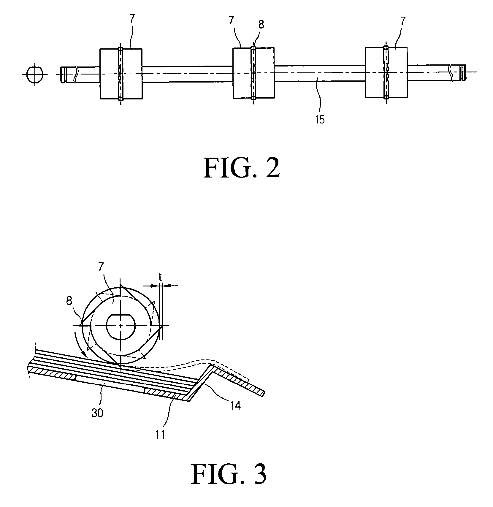
[0051]FIG. 3 is a cross-sectional view of an automatic paper feeding roller according to the third embodiment of the present invention.
[0052]Referring to FIG. 3, the automatic paper feeding roller 7 is formed as a circular shape, and a plurality of supply protrusions 8 are formed around an outer circumference of the automatic paper feeding roller 7. The supply protrusion protrudes outward to a certain length. Paper sheets (P) placed on the paper feeding tray 11 are simultaneously conveyed in plurality only when caught by the supply protrusion 8 and pass over the stepped protrusion 14. When the paper sheets caught by the supply protrusion 8 are conveyed, they are pushed in contact with an outer ...
PUM
| Property | Measurement | Unit |
|---|---|---|
| dynamic force | aaaaa | aaaaa |
| outer circumference | aaaaa | aaaaa |
| speed | aaaaa | aaaaa |
Abstract
Description
Claims
Application Information
 - R&D
- Intellectual Property
- Life Sciences
- Materials
- Tech Scout
- Unparalleled Data Quality
- Higher Quality Content
- 60% Fewer Hallucinations
Browse by: Latest US Patents, China's latest patents, Technical Efficacy Thesaurus, Application Domain, Technology Topic, Popular Technical Reports.
© 2025 PatSnap. All rights reserved.Legal|Privacy policy|Modern Slavery Act Transparency Statement|Sitemap|About US| Contact US: help@patsnap.com


