Apparatus and method for second-layer through-bushing inspection of aircraft wing attachment fittings using electric current perturbation

a technology of electric current perturbation and aircraft wing attachment, which is applied in the direction of soldering apparatus, instruments, manufacturing tools, etc., to achieve the effect of accurate assessment of integrity and minimal steel interference in the inspection area

Active Publication Date: 2009-03-10
SOUTHWEST RES INST
View PDF12 Cites 2 Cited by
  • Summary
  • Abstract
  • Description
  • Claims
  • Application Information

AI Technical Summary

Benefits of technology

[0011]In the present invention, a specially designed, contact compliant, Electric Current Perturbation (ECP) probe is used. The ECP probe positions a receive coil in conjunction with a drive coil (and its ferrite core) in a manner that minimizes steel interferences in the inspection area. The ECP probe works with conventional eddy current instrumentation with an index scanner to allow for flaw location within a particular stack-up layer. Data acquired through the use of the system and method of the present invention allows for the rapid discernment of flaws and defects in the area adjacent the probe placement.
[0012]The methods and probe structures of the present invention therefore provide an inspection technique that allows for an accurate assessment of the integrity of an aircraft wing attachment fitting, even one that has been modified to extend its life, without the need to remove the entire wing structure from the aircraft fuselage.

Problems solved by technology

Such aircraft life extension programs often result in the placement of fitting stack-up components that tend to challenge the ability of standard inspection sensors and techniques to achieve accurate readings.

Method used


Image

  • Apparatus and method for second-layer through-bushing inspection of aircraft wing attachment fittings using electric current perturbation
  • Apparatus and method for second-layer through-bushing inspection of aircraft wing attachment fittings using electric current perturbation
  • Apparatus and method for second-layer through-bushing inspection of aircraft wing attachment fittings using electric current perturbation

Examples


Embodiment Construction

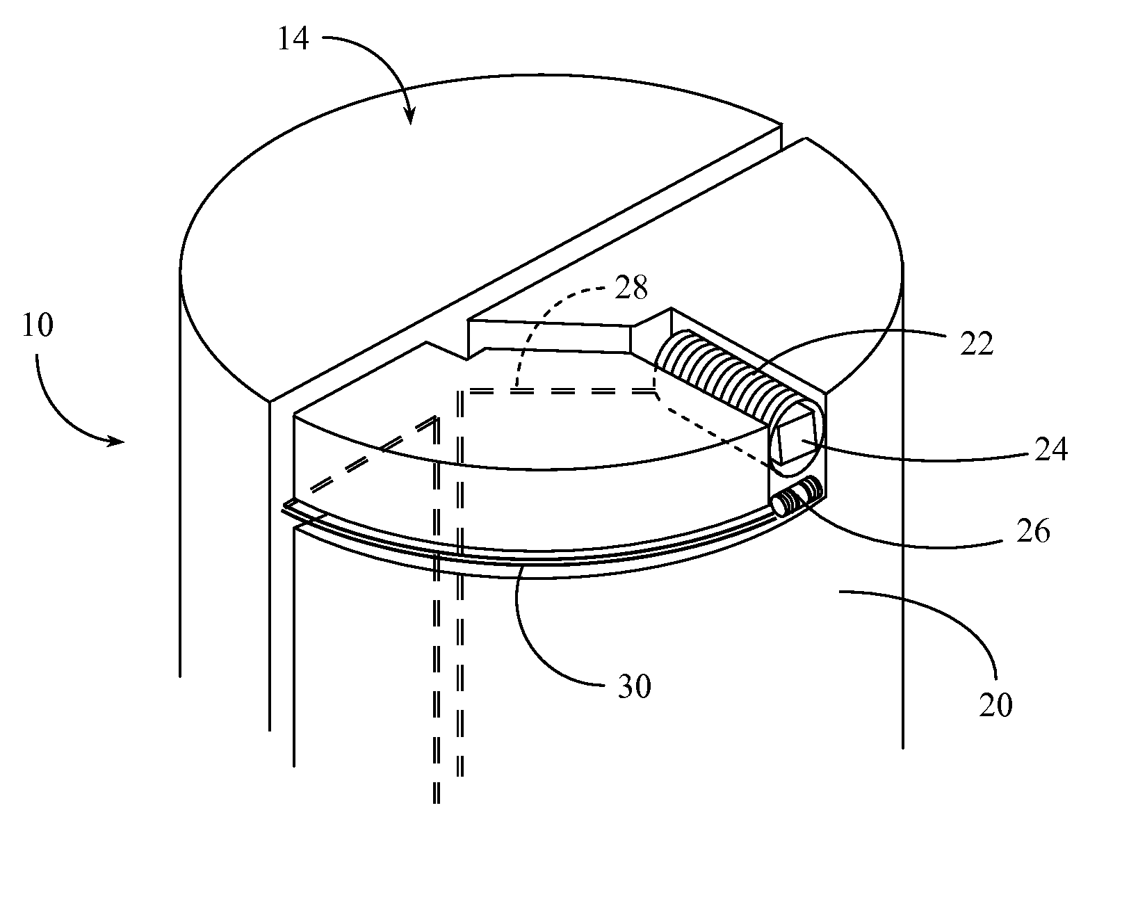
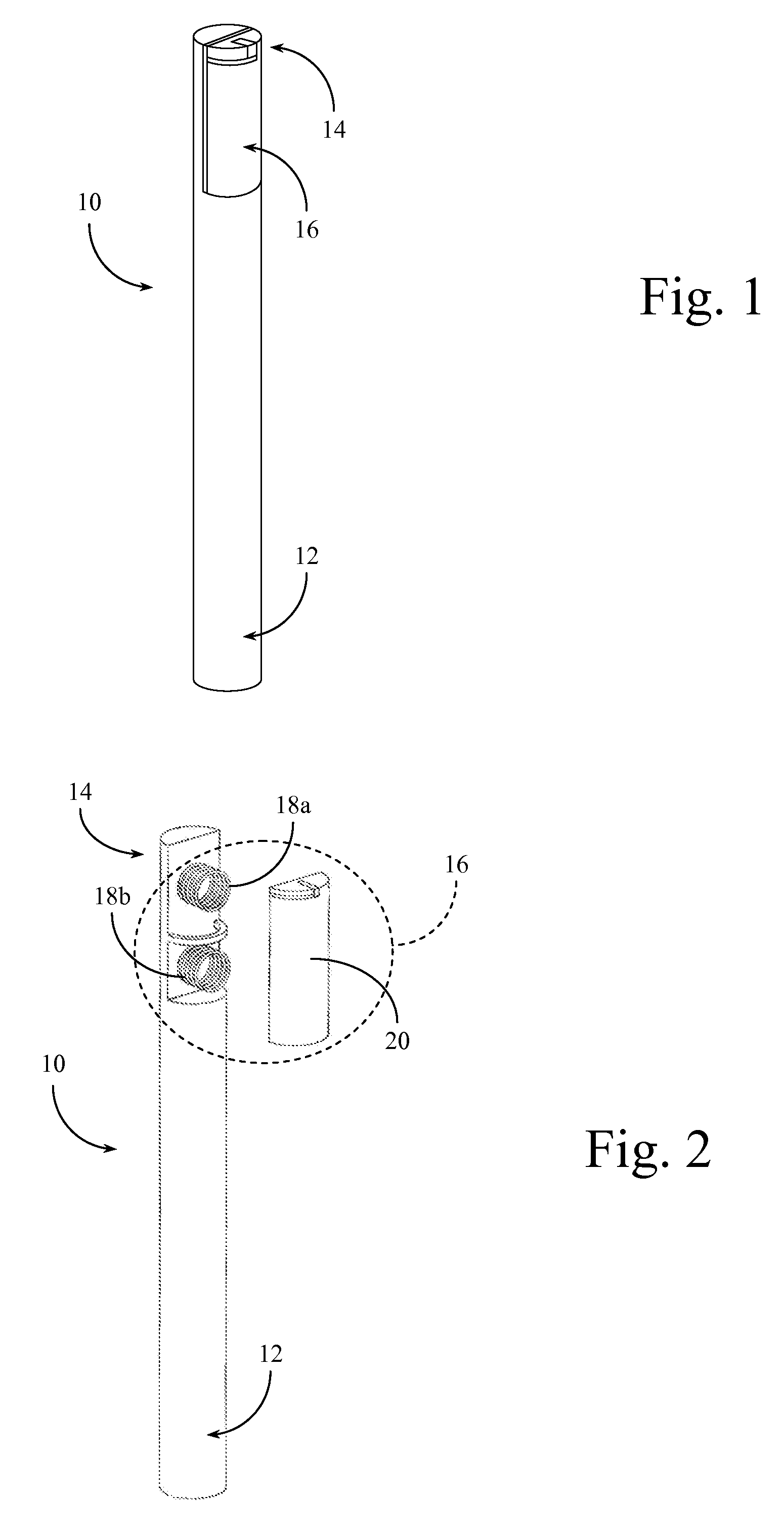
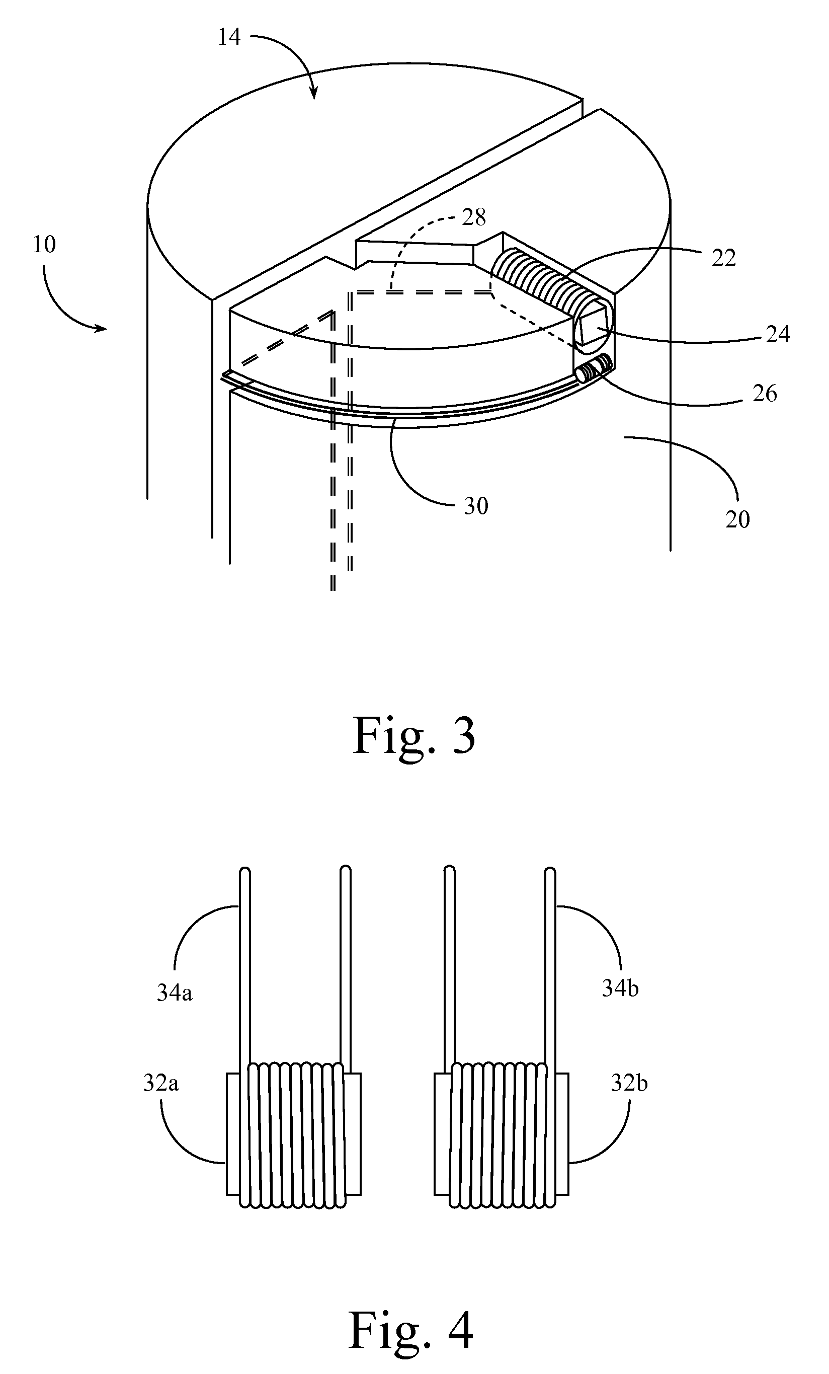
[0023]The basis of the system and method of the present invention revolves around the design of an Electric Current Perturbation (ECP) compliant probe (see in particular FIGS. 1 and 2), capable of adjusting to the surface inside dimension of the fastener hole. This probe uses a drive coil and a differential receive coil arrangement (see in particular FIGS. 3 and 4), that significantly improve the sensor discrimination. The receive coil is advantageously positioned below the drive coil. The positioning of the receive coil to the drive coil helps minimize magnetic steel interferences of the inspection area at the receive coil by using the ferrite core of the drive coil as a shield. This arrangement increases the sensitivity to defects of the probe with both a standard attachment fitting configuration and with a Structural Life Extension Program (SLEP)-modified wing attachment fitting stack-up (see for example FIGS. 5 and 6).

[0024]In standard practice, a structural crack adjacent a fit...


PUM

PropertyMeasurementUnit
electric current perturbationaaaaaaaaaa
electrical currentaaaaaaaaaa
electrical signalaaaaaaaaaa

Abstract

A device and methods for using the device, that permit the rapid and accurate inspection of aircraft wing attachment fittings, including those wing to fuselage attachments modified according to a Structural Life Extension Program (SLEP). Such aircraft life extension programs often result in the placement of fitting stack-up components that tend to challenge the ability of standard inspection sensors and techniques to achieve accurate readings. A specially designed, contact compliant, Electric Current Perturbation (ECP) probe is used. The ECP probe positions a receive coil in conjunction with a drive coil (and its ferrite core) in a manner that minimizes steel interferences in the inspection area. The ECP probe works with conventional eddy current instrumentation with an index scanner to allow for flaw location within a particular stack-up layer and / or within the area around the attachment aperture. Data acquired through the use of the system and method of the present invention allows for the rapid discernment of flaws and defects in the area adjacent the probe placement.

Description

CROSS REFERENCE TO RELATED APPLICATIONS[0001]This application claims the benefit under Title 35 United States Code § 119(e) of U.S. Provisional Application No. 60 / 842,839 filed Sep. 7, 2006, the full disclosure of which is incorporated herein by reference.GOVERNMENT RIGHTS[0002]The U.S. government has a paid-up license in this invention and the right in limited circumstances to require the patent owner to license others on reasonable terms as provided for by the terms of contract number F42620-00-D-0037 awarded by the Department of Defense (DOD-USAF).BACKGROUND OF THE INVENTION[0003]1. Field of the Invention[0004]The present invention relates generally to devices and methods for the non-destructive inspection of structural systems. The present invention relates more specifically to devices and methods for the inspection of aircraft structural systems, particularly those associated with the attachment of a wing structure to an aircraft fuselage.[0005]2. Description of the Related Art...

Claims


Application Information

Patent Timeline
Patent Type & Authority Patents(United States)
IPC IPC(8): G01N27/82
CPCG01N27/87
Inventor THWING, CLINTON J.BURKHARDT, GARY L.
Owner SOUTHWEST RES INST
Why Eureka
Try Eureka