Profile roof tile with integrated photovoltaic module

a photovoltaic module and roof tile technology, applied in the field of solar panels, can solve the problems of significant construction problems, solar panels that were not permitted, and flat solar panels

Inactive Publication Date: 2009-03-24
LUMETA LLC
View PDF38 Cites 98 Cited by
  • Summary
  • Abstract
  • Description
  • Claims
  • Application Information

AI Technical Summary

Benefits of technology

[0014]The profile (contoured) solar panel tile described herein and illustrated in the attached drawings enables the electricity-generating solar panel to be included in a seamless application with any conventional profile tile because the solar panel is advantageously embodied in a shape and size of a conventional profile tile, such as, for example, a concrete or clay “S” tile, a concrete low-profile tile, or a profile tile constructed from other materials or in other shapes. As discussed herein, the size and shape of the profile solar panel tile may be adapted to the size and shape of profile tiles from a number of different manufacturers. The size and shape of the profile solar panel tile enables the same roofing mechanic who installs the conventional roofing tiles to install the profile solar panel tile without any special tools or fasteners. In particular, the profile solar panel tiles have crests and valleys that conform to the crests of valleys of conventional tiles in adjacent courses (e.g., conventional tiles above or below the profile solar panel tiles). The profile solar tiles also interlock with or overlap with adjacent conventional tiles when installed in the same course. The adjacent tiles may be other profile solar panel tiles or conventional profile roofing tiles.

Problems solved by technology

Originally, the solar panels were mounted over existing roofing materials (e.g., shingles) and formed a generally unaesthetic addition to a home.
In some areas, the solar panels were not permitted because of the unattractive appearance.
The flat solar panels create significant construction issues at the transitions between the profile tiles and the flat solar panels.

Method used


Image

  • Profile roof tile with integrated photovoltaic module
  • Profile roof tile with integrated photovoltaic module
  • Profile roof tile with integrated photovoltaic module

Examples


Embodiment Construction

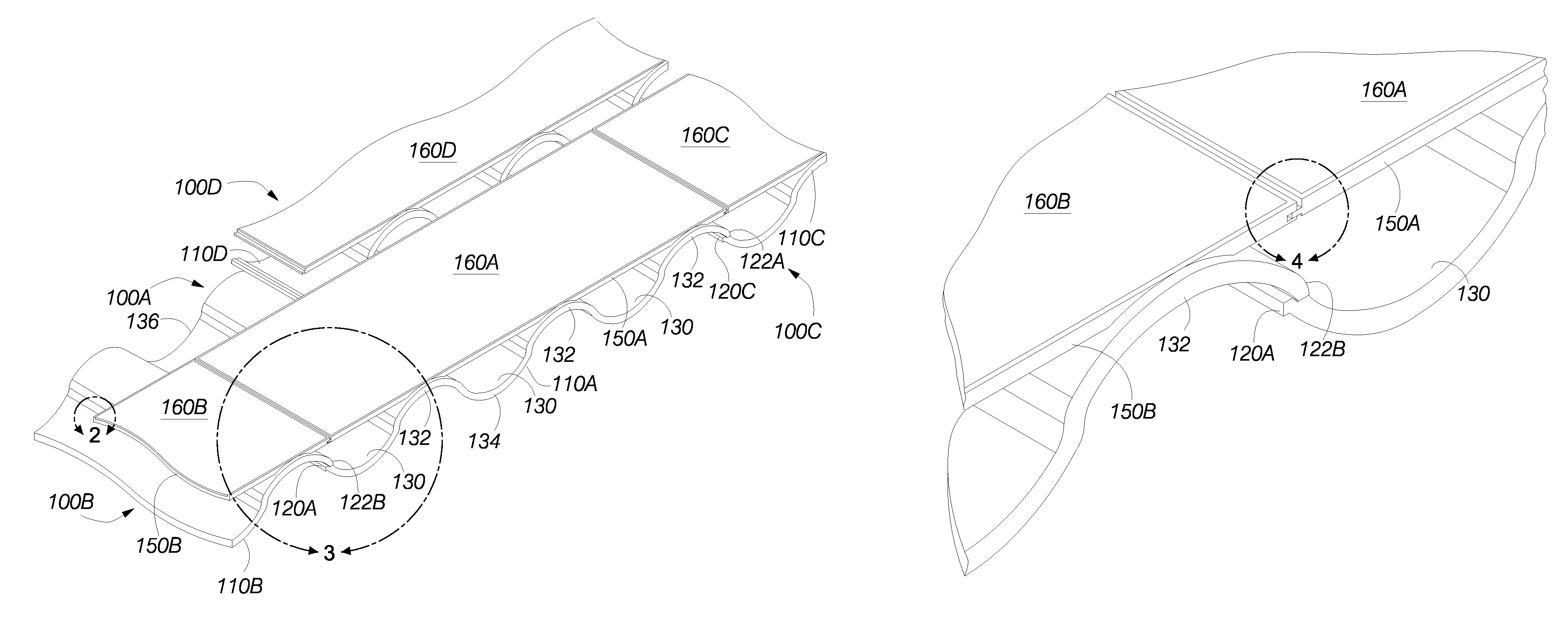
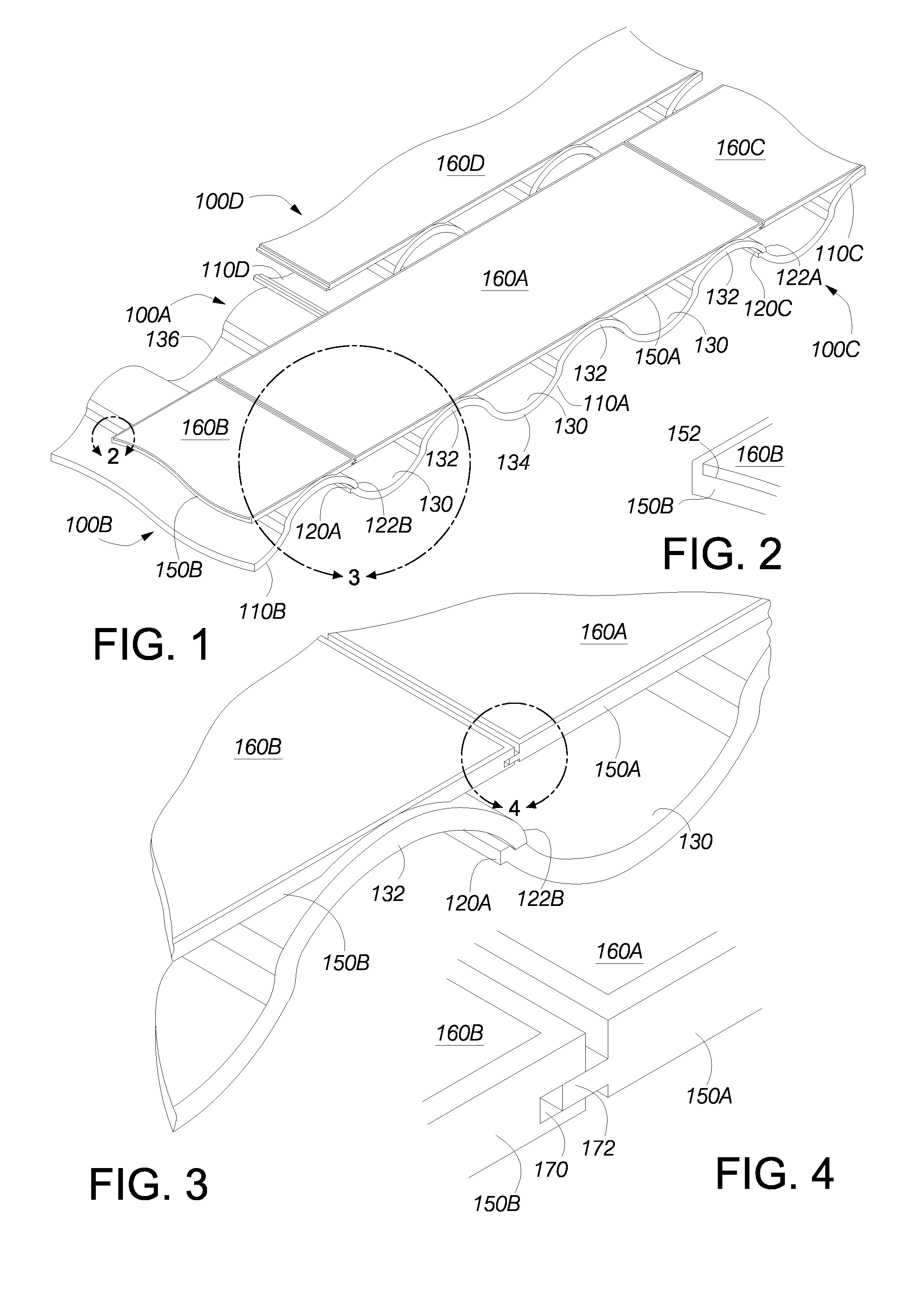
[0040]FIG. 1 illustrates a first profile (contoured) solar panel tile 100A in accordance with aspects of the present invention. FIG. 1 further illustrates a portion of a second profile solar panel tile 100B positioned at the left end of the first profile solar panel tile 100A and a portion of a third profile solar panel tile 100C positioned at the right end of the first profile solar panel tile 100A. As further illustrated in FIG. 1, a portion of a fourth profile solar panel tile 100D has a lower edge that overlaps the upper edges of portions of the first profile solar panel tile 100B and the third profile solar panel tile 100C.

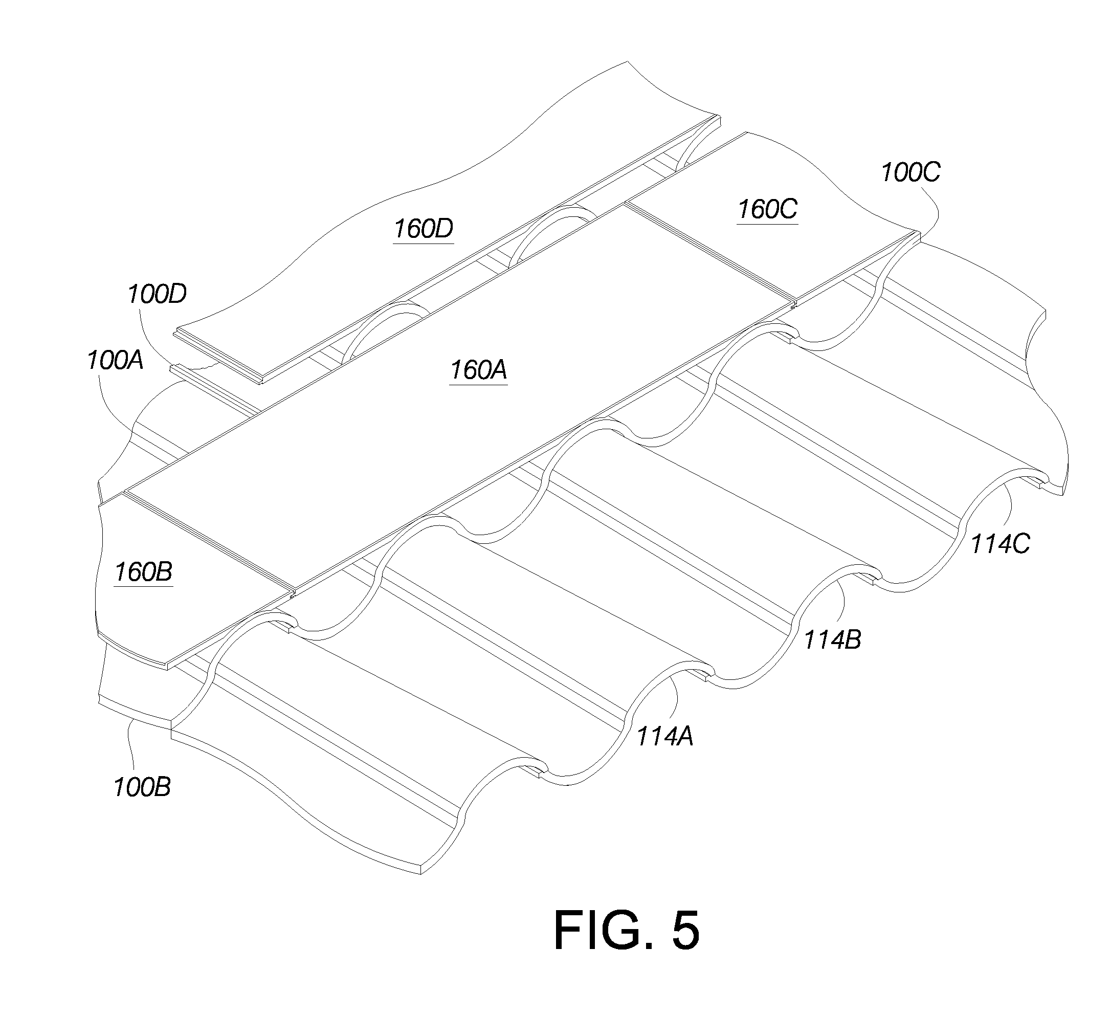
[0041]In the embodiment illustrated in FIG. 1, the profile solar panel tile 100A comprises a profile structure 110A (also referred to herein as a tile base) that is sized and shaped to conform to the approximate size and shape of a plurality (e.g., three) of abutting conventional profile tiles (“S” tiles) 114A, 114B, 114C when positioned on the roof of a buil...


PUM

PropertyMeasurementUnit
widthaaaaaaaaaa
widthaaaaaaaaaa
heightaaaaaaaaaa

Abstract

A roofing module provides weather protection generates electrical power. The module comprises a base having a plurality of curved crests and curved pans. The crests and pans have contours sized and shaped to match the size and shape of the contours and pans of conventional clay or concrete S-tiles to enable the base to interlock with the conventional clay or concrete S-tiles. The base is made from lightweight plastic material. Each crest of the base includes a depressed portion. A photovoltaic panel is positioned in the depressed portions of at least two curved crests and span across at least one curved pan between the at least two curved crests.

Description

RELATED APPLICATIONS[0001]The present application is a continuation-in-part application of U.S. patent application Ser. No. 11 / 620,564, filed on Jan. 5, 2007. The present application claims the benefit of priority under 35 U.S.C. § 119(e) to the following provisional applications:[0002]U.S. Provisional Application No. 60 / 806,445, filed on Jun. 30, 2006;[0003]U.S. Provisional Application No. 60 / 806,528, filed on Jul. 3, 2006;[0004]U.S. Provisional Application No. 60 / 807,501, filed on Jul. 17, 2006;[0005]U.S. Provisional Application No. 60 / 820,334, filed on Jul. 25, 2006[0006]U.S. Provisional Application No. 60 / 871,988, filed on Dec. 27, 2006; and[0007]U.S. Provisional Application No. 60 / 940,432, filed on May 28, 2007.BACKGROUND OF THE INVENTION[0008]1. Field of the Invention[0009]The present invention relates to solar panels for generating electrical energy and more particularly relates to solar modules integrated into profile (contoured) roof tiles.[0010]2. Description of the Relate...

Claims


Application Information

Patent Timeline
Patent Type & Authority Patents(United States)
IPC IPC(8): E04D13/18E04B1/00H01L31/042
CPCE04D1/08E04D1/30E04D3/32F24J2/5228H02S20/25H02S20/23Y02B10/20Y02E10/47Y02B10/12E04D1/265F24S25/40F24S2025/601H01L31/042H02S40/34Y02B10/10Y02E10/50
Inventor FLAHERTY, BRIAN J.DAVEY, TIMOTHY M.
Owner LUMETA LLC
Why Eureka
Try Eureka