Sealed upscale total containment vessel

a total containment and seal technology, applied in the direction of solid waste disposal, chemical equipment and processes, weapons, etc., can solve the problems of extreme harmful and potential of improvised explosive devices, and achieve the effect of reducing the size of the reinforcing ring, reducing the size of the sealing system, and eliminating the inflatable seal

Inactive Publication Date: 2009-03-24
MISTRAL
View PDF34 Cites 17 Cited by
  • Summary
  • Abstract
  • Description
  • Claims
  • Application Information

AI Technical Summary

Benefits of technology

[0010]Inflatable seals of a conventional UTCV are replaced with large o-rings. Preferably, three o-rings are used to maintain redundancy in the system. A first o-ring is located in a valley in a opening support ring. The primary purpose of the first o-ring is to suppress flames and hot gasses generated during the detonation and to protect a second and third o-ring. The second and third o-rings are located in a door support ring and provide a redundant sealing mechanism. The door support ring also has a ridge that protrudes from a surface of the door support ring and mates with the valley in the opening support ring. This ridge and mating valley also serve to mitigate the flames and hot gasses, as well as protect the second and third o-rings from the blast load.
[0012]The present invention eliminates the 16 bolt closing system on the prior art TCV. The present invention has a simplified sealing system and eliminates inflatable seals. The present invention allows for a fully automated door and closing mechanism. The present invention allows for a reduced size in a vessel reinforcing ring and an enlarged opening. The present invention eliminates the internal door of the prior art TCV.

Problems solved by technology

One particular concern that has extremely harmful results is the potential of an improvised explosive device (IED) that has a biological or chemical agent associated with it.
In a sealed blast containment vessel, a challenging aspect is the complete containment of the high pressure atmosphere during a detonation without any (or extremely low levels of) leakage.

Method used


Image

  • Sealed upscale total containment vessel
  • Sealed upscale total containment vessel
  • Sealed upscale total containment vessel

Examples


Embodiment Construction

[0021]A complete understanding of the invention will be obtained from the following description when taken in connection with the accompanying drawing figures wherein like reference characters identify like parts throughout.

[0022]For purposes of the description hereinafter, the terms “upper”, “lower”, “right”, “left”, “vertical”, “horizontal”, “top”, “bottom”, and derivatives thereof shall relate to the invention as it is oriented in the drawing figures. However, it is to be understood that the invention may assume various alternative variations and step sequences, except where expressly specified to the contrary. It is also to be understood that the specific devices and processes illustrated in the attached drawings, and described in the following specification, are simply exemplary embodiments of the invention. Hence, specific dimensions and other physical characteristics related to the embodiments disclosed herein are not to be considered as limiting.

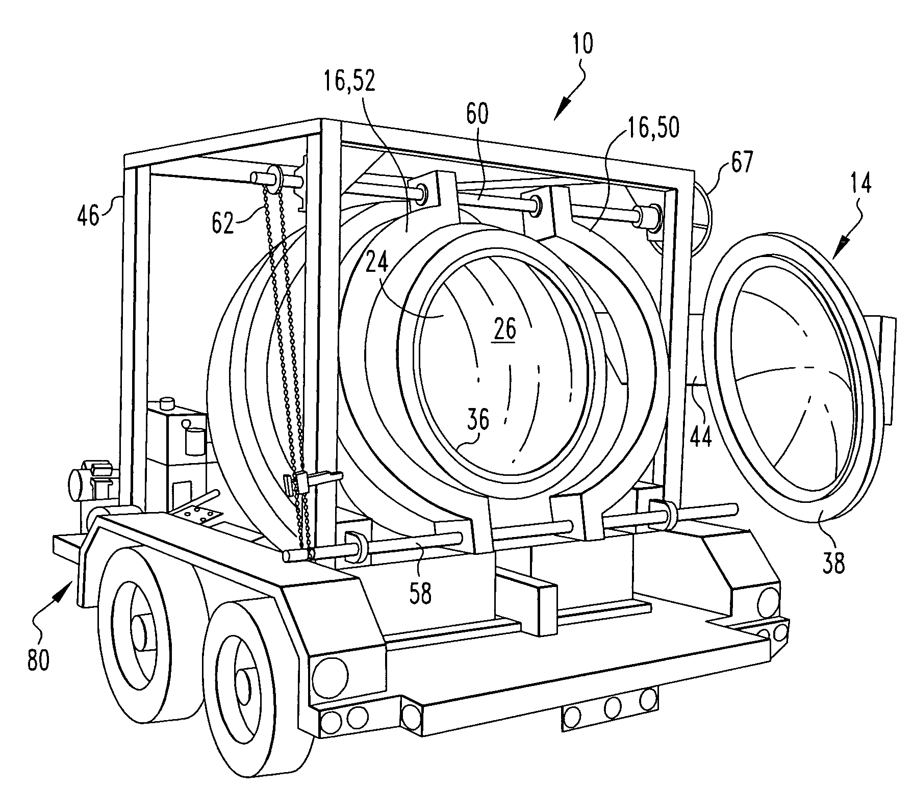
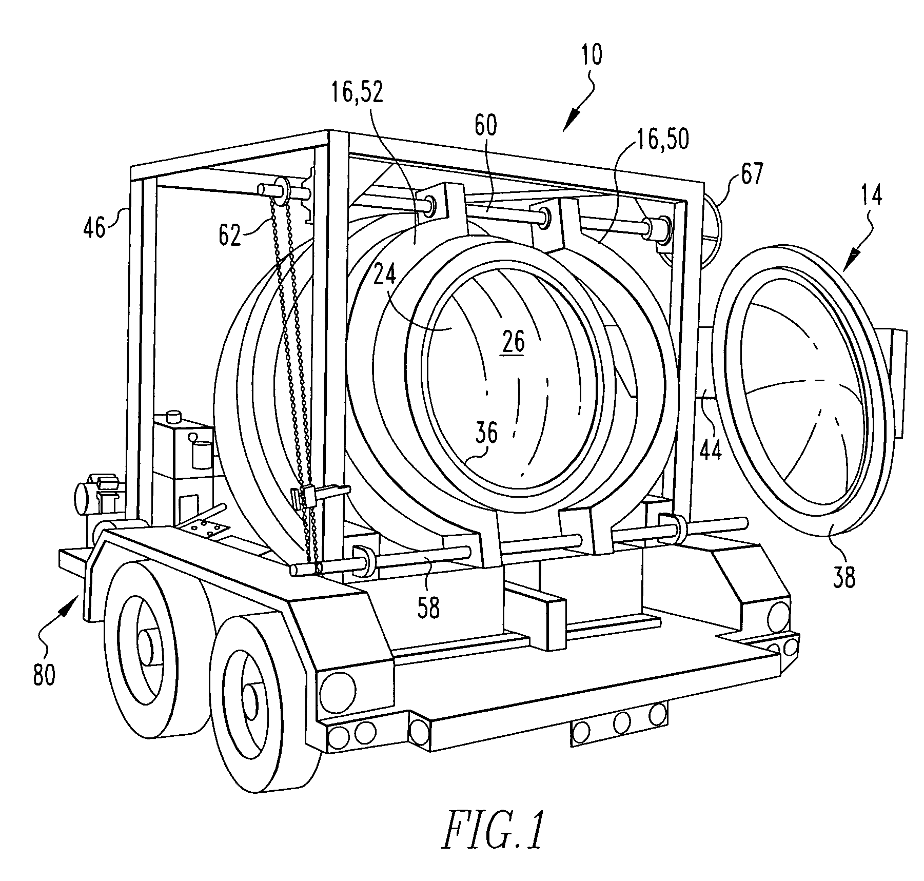
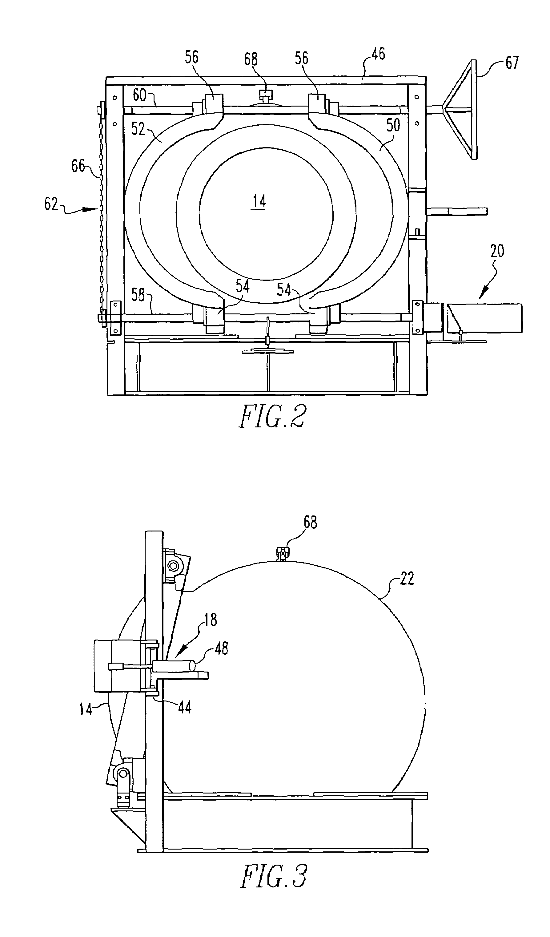
[0023]Referring to FIGS. 1-5,...


PUM


Abstract

Disclosed is a blast containment vessel. A body has an opening. An external door is configured to form a seal surrounding the opening when the external door is in a closed position. A yoke is configured to retain the door in the closed position. A first automatic system is configured to automatically move the external door into and out of the closed position. A second automatic system is configured to automatically move the yoke when the external door is in the closed position. During and after a blast event, the body and the external door contain products of the blast event and the seal remains intact.

Description

CROSS-REFERENCE TO RELATED APPLICATIONS[0001]This application claims the benefit of U.S. Provisional Patent Application Ser. No. 60 / 517,632, filed Nov. 5, 2003.BACKGROUND OF THE INVENTION[0002]1. Field of the Invention[0003]The present invention is directed to a blast containment vessel, and more particularly, to a containment vessel that can be used for the safe containment, transportation, and disposal of an explosive device having a biological or chemical agent associated with it.[0004]2. Description of Related Art[0005]Increased terrorist incidents have heightened awareness of the vulnerability to potential terrorist activity and the terrorist's willingness to strike targets in the United States. One particular concern that has extremely harmful results is the potential of an improvised explosive device (IED) that has a biological or chemical agent associated with it. Thus, a need exists for blast containment vessels that can be used for the safe containment, transportation, and...

Claims


Application Information

Patent Timeline
Patent Type & Authority Patents(United States)
IPC IPC(8): F42B33/00
CPCF42B33/06F42D5/045Y10S588/90
Inventor KING, KIM W.
Owner MISTRAL
Why Eureka
Try Eureka