Data storage system and data storage control device

a data storage system and control device technology, applied in the direction of error detection/correction, input/output to record carriers, instruments, etc., can solve the problems of waste, increased device size, poor idea of increasing the number of ports, etc., and achieve the effect of low latency

Inactive Publication Date: 2014-08-07
FUJITSU LTD
View PDF20 Cites 2 Cited by
  • Summary
  • Abstract
  • Description
  • Claims
  • Application Information

AI Technical Summary

Benefits of technology

[0032]With the foregoing in view, it is an object of the present invention to provide a data storage system and data storage control device for performing data transfer among each unit at high throughput, and easily implementing a small scale to large scale configuration without causing mounting problems.
[0033]It is still another object of the present invention to provide a data storage system and data storage control device having the flexibility to easily implement a small scale to large scale configuration in a combination of same units, while maintaining redundancy which enables operation even if one unit fails.
[0034]It is still another object of the present invention to provide a data storage system and data storage control device for easily implementing a small scale to large scale configuration without causing mounting problems while maintaining high throughput and redundancy.
[0045]In the present invention, it is also preferable that the cache control unit and the first interface unit are connected by a high-speed serial bus with low latency.
[0046]In the present invention, the second interface of each control module and the plurality of first switch units are connected, so all the control modules can maintain redundancy to access all the storage devices, and even if the number of control modules increases, the control modules and first switch units are connected by a serial bus, which has a small number of signals constituting the interface, using a back panel, so mounting on the printed circuit board is possible.

Problems solved by technology

This means that the size of the device increases.
Increasing the number of ports is also a poor idea since a sufficient redundant structure can be implemented for one disk enclosure only if there are two systems of paths.
Also the number of disk adapters to be connected is not constant, but changes according to user demands, so if many ports are extended, waste is generated if a small number of disk adapters are used, but if few ports are extended, these cannot support many disk adapters.
In other words flexibility is lost.
Also in the case of the disk array device 100, the number of connection lines between the cache managers 10 and routers 14 sharply increases if a large scale disk array device having many major units is constructed, and this makes the connection relationship complicated and mounting becomes physically difficult.
Therefore the printed circuit board of the back panel 15 requires 24 layers, which is four times the above case, of which implementation is difficult.
However where the PCI bus runs at 66 MHz, the PCI-Express bus is a 2.5 Gbps high-speed bus, and in order to maintain the signal quality of a high-speed bus, expensive substrate material must be used.
For example, a board requires 12 signal layers, and these must be constructed using expensive material, therefore this is also difficult to be implemented.

Method used


Image

  • Data storage system and data storage control device
  • Data storage system and data storage control device
  • Data storage system and data storage control device

Examples


Embodiment Construction

[0060]Embodiments of the present invention will now be described in the sequence of the data storage system, read / write processing, mounting structure and other embodiments.

Data Storage System

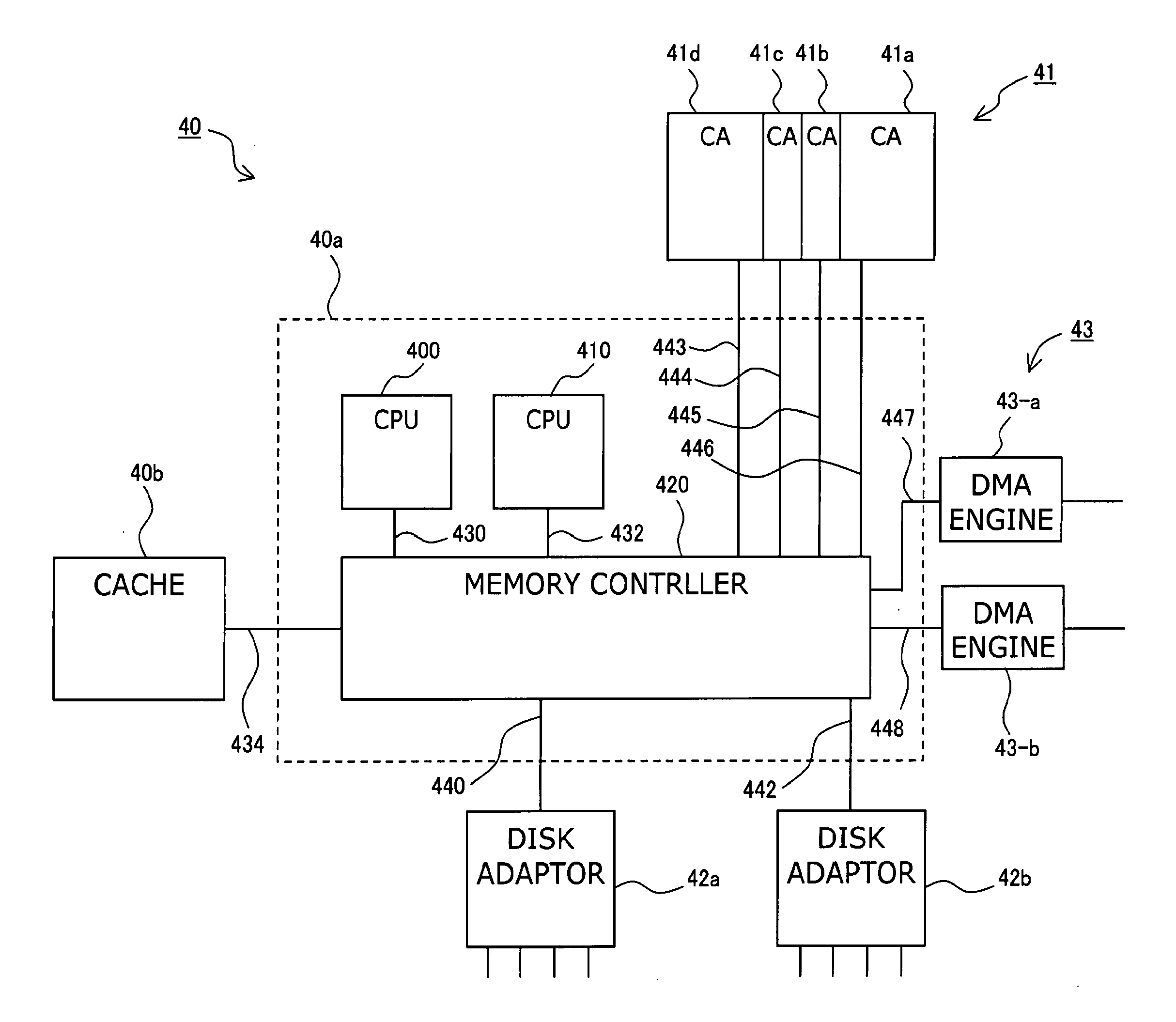
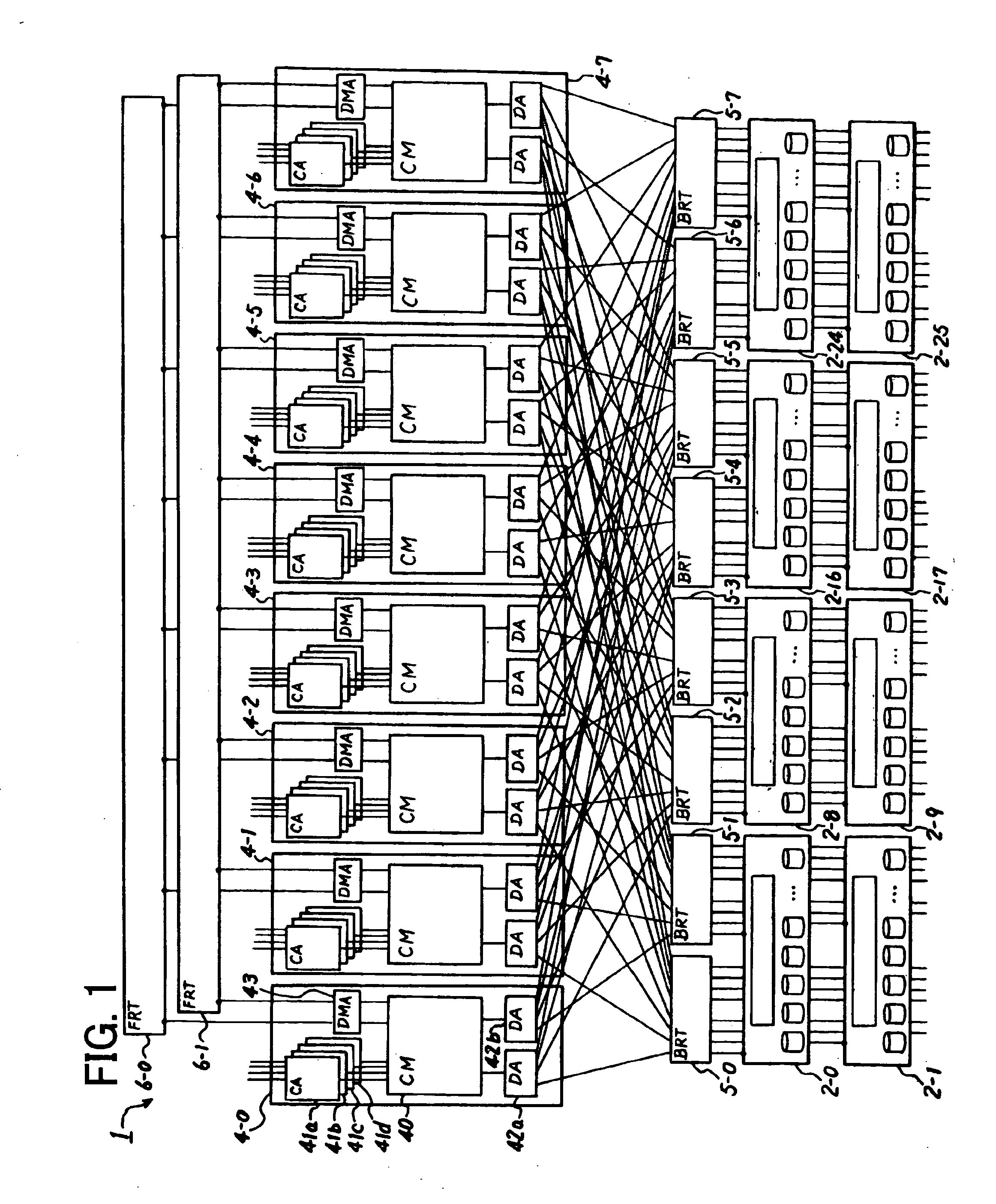
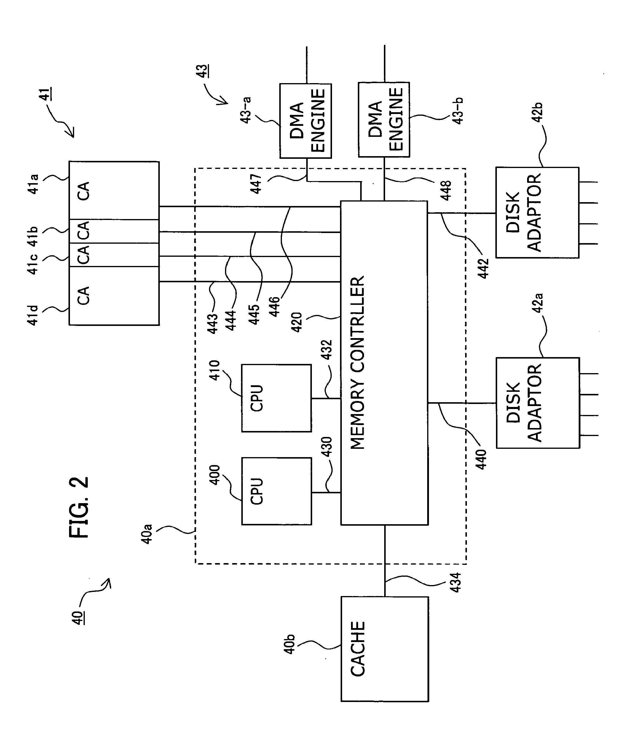
[0061]FIG. 1 is a block diagram depicting the data storage system according to an embodiment of the present invention, FIG. 2 is a block diagram depicting the control module in FIG. 1, FIG. 3 is a block diagram depicting the back end routers and disk enclosures in FIG. 1, and FIG. 4 is a block diagram depicting the disk enclosures in FIG. 1 and FIG. 3.

[0062]FIG. 1 shows a large scale storage system having eight control modules as an example. As FIG. 1 shows, the storage system 1 has a plurality of disk enclosures 2-0-2-25 for holding data, a plurality of (eight in this case) of control modules 4-0-4-7 disposed between the host computers (data processing units), which are not illustrated, and a plurality of disk enclosures 2-0-2-25, a plurality (eight in this case) of back end routers (first swi...


PUM


Abstract

A storage system has a plurality of control modules for controlling a plurality of storage devices, which make mounting easier with maintaining low latency response even if the number of control modules increases. A plurality of storage devices are connected to the second interface of each control module using back end routers, so that redundancy for all the control modules to access all the storage devices is maintained. Also the control modules and the first switch units are connected by a serial bus, which has a small number of signals, constituting the interface by using the back panel. By this, mounting on the printed circuit board becomes possible.

Description

CROSS-REFERENCE TO RELATED APPLICATIONS[0001]This application claims the benefit of and is a continuation of U.S. application Ser. No. 11 / 138,299, filed May 27, 2005, which is based upon and claims the benefit of priority from the prior Japanese Patent Application No. 2004-347411, filed on Nov. 30, 2004, and the prior Japanese Patent Application No. 2005-022121, filed on Jan. 28, 2005, the entire contents of which are incorporated herein by reference.BACKGROUND OF THE INVENTION[0002]1. Field of the Invention[0003]The present invention relates to a configuration of a data storage system and a data storage control device which are used for an external storage device of a computer, and more particularly to a data storage system and a data storage control device having a combination and connection of units which can construct a data storage system connecting many disk devices with high performance and flexibility.[0004]2. Description of the Related Art[0005]Recently as various data is c...

Claims


Application Information

Patent Timeline
Patent Type & Authority Applications(United States)
IPC IPC(8): G06F3/06G06F12/0866
CPCG06F3/0689G06F3/0665G06F3/0619G06F3/0605G06F3/0629G06F3/0683G06F11/201G06F11/2089G06F12/0866G06F3/06
Inventor OHARA, SHIGEYOSHIMASUYAMA, KAZUNORI
Owner FUJITSU LTD
Why Eureka
Try Eureka