Storage system
a storage system and storage technology, applied in the field of storage systems, can solve the problems of high-capacity storage systems, data to be stored has increased day by day, and the amount of data has become huge, so as to achieve high speed and maintain redundancy
- Summary
- Abstract
- Description
- Claims
- Application Information
AI Technical Summary
Benefits of technology
Problems solved by technology
Method used
Image
Examples
first exemplary embodiment
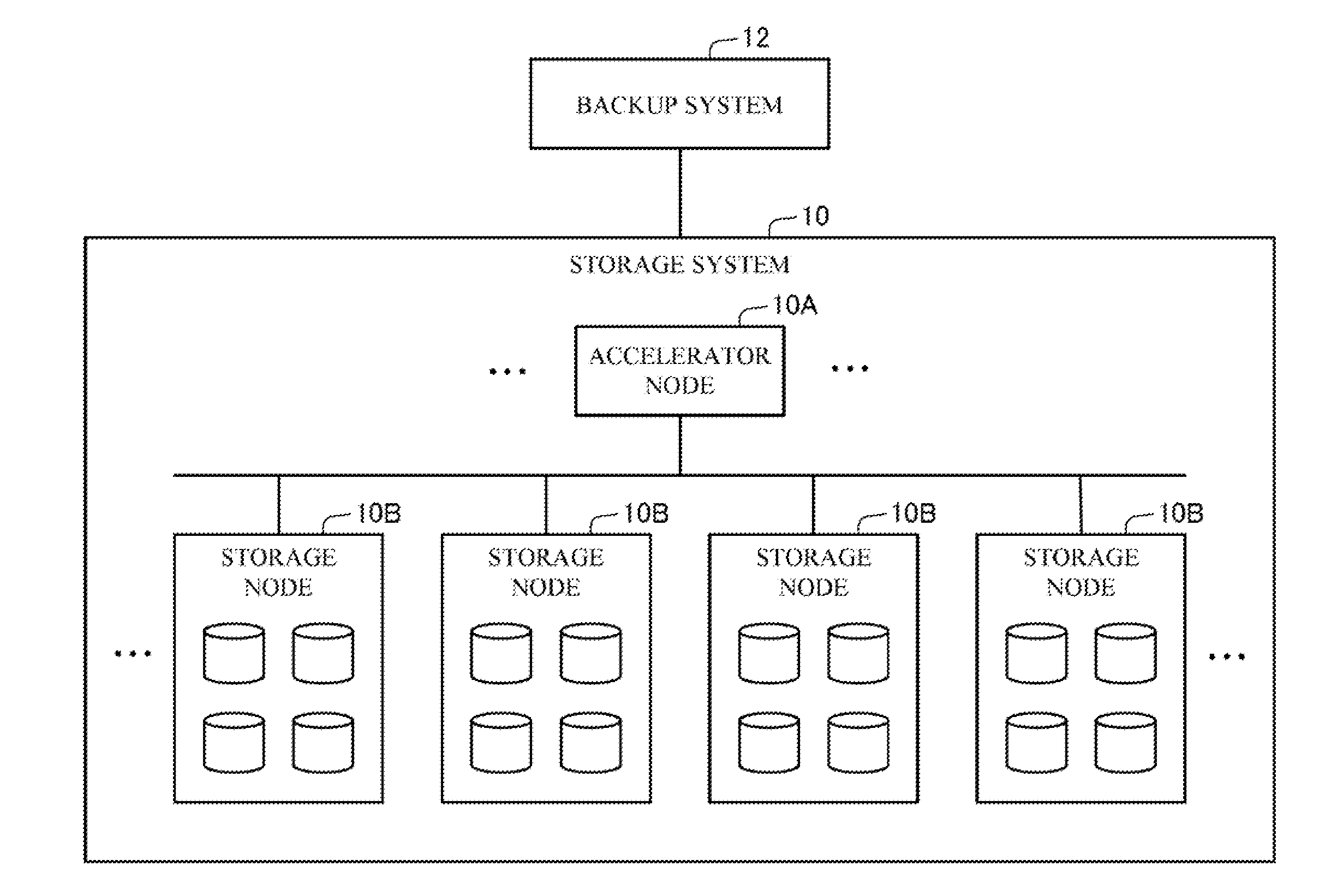
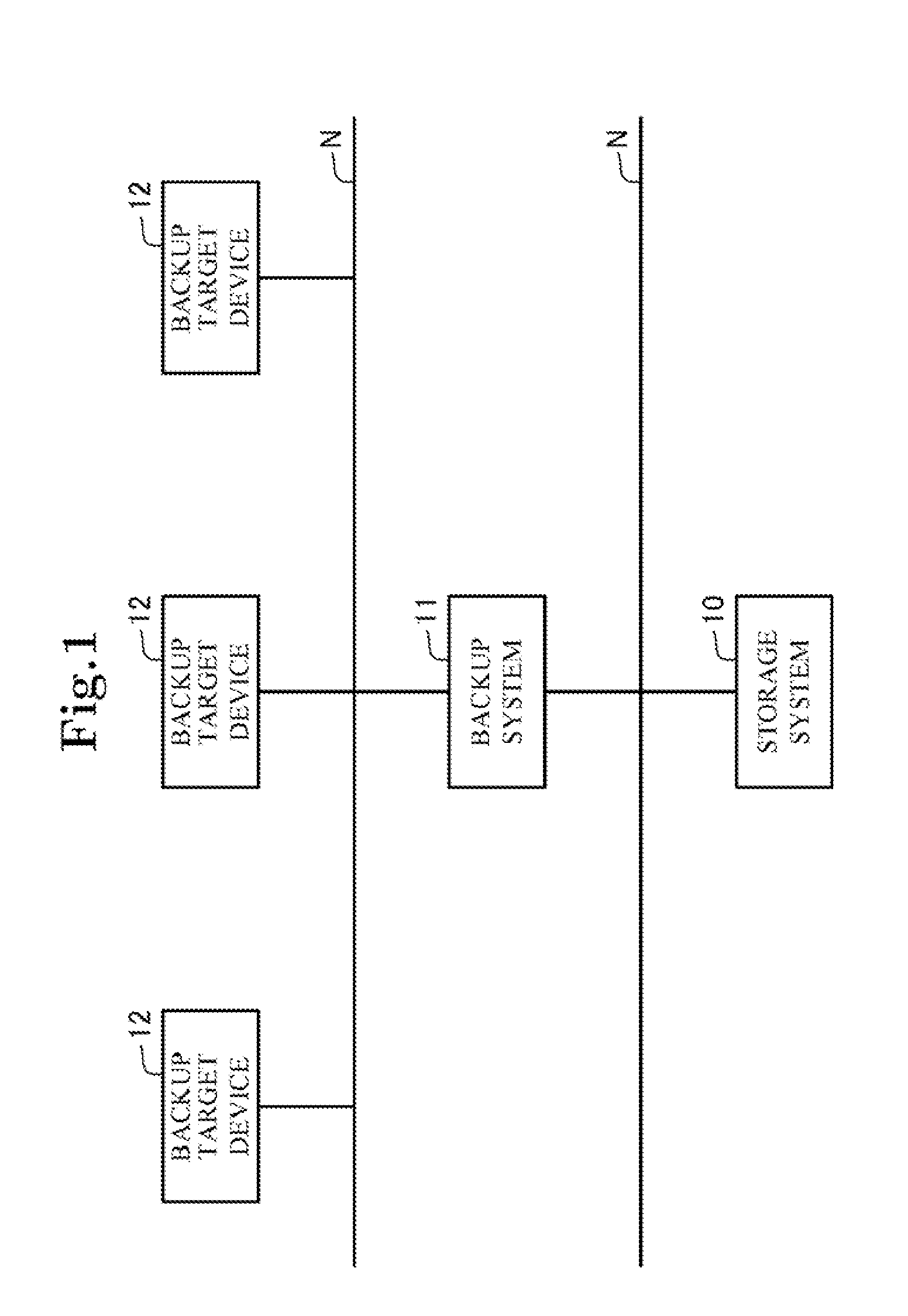
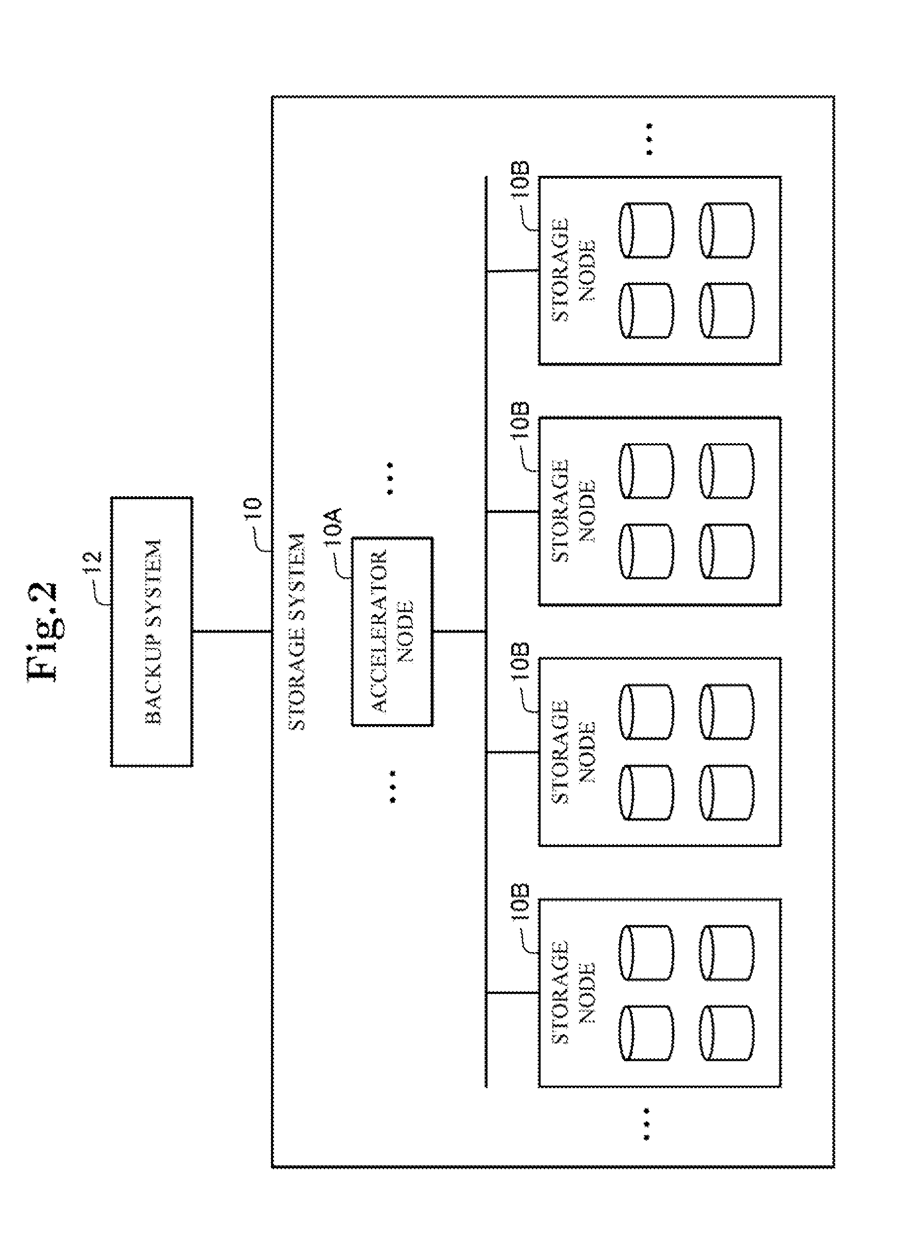
A first exemplary embodiment of the present invention will be described with reference to FIGS. 1 to 9. FIG. 1 is a block diagram showing a configuration of a whole system. FIG. 2 is a block diagram schematically showing a storage system, and FIG. 3 is a function block diagram showing the configuration. FIGS. 4 to 6 are explanation views for explaining an operation of a storage system. FIGS. 7 and 8 are views showing a data storage state in the storage system. FIG. 9 is a flowchart showing an operation of the storage system.
This exemplary embodiment herein shows a specific example of a storage system disclosed in a third exemplary embodiment described later. Below, a case that the storage system is configured by connecting a plurality of server computers will be described. However, the storage system of the present invention is not limited to the configuration with a plurality of computers, and may be configured by one computer.
[Configuration]
As shown in FIG. 1, a storage system 10 ...
second exemplary embodiment
Next, a second exemplary embodiment of the present invention will be described with reference to FIGS. 10 to 17. FIG. 10 is a function block diagram showing a configuration of a storage system. FIGS. 11 to 16 are explanation views for explaining an operation of the storage system. FIG. 17 is a flowchart showing an operation of the storage system.
[Configuration]
As shown in FIG. 10, a storage system 10 of this exemplary embodiment employs almost the same configuration as that of the first exemplary embodiment described above. In this exemplary embodiment, the storage system 10 is equipped with a stream ID provision unit 26 configured by installing a program into the data processing device 20. According to this, the distribution storage control unit 24, etc. have different configurations. Below, a different point from the first exemplary embodiment will be described mainly. The aforementioned program is provided to the storage system 10 by a storage medium such as a CD-ROM, or provided...
third exemplary embodiment
A third exemplary embodiment of the present invention will be described with reference to FIG. 18. FIG. 18 is a function block diagram showing a configuration of a storage system. In this exemplary embodiment, the storage system will be schematically described.
As shown in FIG. 18, a storage system 1 of this exemplary embodiment is equipped with a plurality of storing means 5 and a data processing means 2 configured to store data into the plurality of storing means 5 and retrieve the data stored in the storing means 5.
Then, the data processing means 2 includes: a data set generating means 3 configured to generate division data by dividing storage target data into a plurality of pieces and also generate redundant data for restoring the storage target data, thereby generating a data set composed of a plurality of fragment data that are the division data and the redundant data; and a distribution storage controlling means 4 configured to distribute and store the fragment data into the r...
PUM
 Abstract
Description
Claims
Application Information
 - R&D
- Intellectual Property
- Life Sciences
- Materials
- Tech Scout
- Unparalleled Data Quality
- Higher Quality Content
- 60% Fewer Hallucinations
Browse by: Latest US Patents, China's latest patents, Technical Efficacy Thesaurus, Application Domain, Technology Topic, Popular Technical Reports.
© 2025 PatSnap. All rights reserved.Legal|Privacy policy|Modern Slavery Act Transparency Statement|Sitemap|About US| Contact US: help@patsnap.com


