Device for decoupling and protection from compensation currents in a redundant system for autonomous driving

a technology of compensation current and device, which is applied in the direction of electric vehicles, braking systems, dc source parallel operation, etc., can solve the problems of redundant configuration of safety-critical electronic systems, insufficient time to assume control of vehicles, and inability of drivers to intervene and assume control of vehicles

Pending Publication Date: 2022-03-24
KNORR-BREMSE SYST FUER NUTZFAHRZEUGE GMBH
View PDF8 Cites 2 Cited by
  • Summary
  • Abstract
  • Description
  • Claims
  • Application Information

AI Technical Summary

Benefits of technology

[0014]Based on the above-mentioned set of problems, an object of the present invention is to prevent compensation currents between voltage supplies via the control units in a compressed-air braking system with redundant control units jointly using solenoid valves, including those without galvanic isolation and in compliance with safety requirements. In addition, the invention is intended to ensure that a fault in a control circuit in a compressed-air braking system does not affect another control circuit.
[0016]The invention is based on a device for decoupling and protection against compensation currents when electric actuators are shared by two independently voltage-supplied control units in redundant systems for autonomous driving. In a modular approach, the invention includes circuit modules (A and B), which can be added to conventional control units and which, in combination with control units, provide protection against compensation currents and feedback effects due to shared usage.
[0021]The features according to the invention as described above, in particular, advantageously prevent a voltage offset or a ground offset from causing an undesirable current flow between control units and / or electronic control devices in a redundantly configured system, such as a braking system, for autonomous driving, which in turn advantageously prevents one or all of the electronic control units from being damaged or destroyed due to the unwanted current flow, or a defective electronic control unit from again being unintentionally supplied “backwards” if, for example, it is disconnected from its supply voltage due to a fault, or the current from an intact electronic control unit from being short-circuited to a solenoid valve if a faulty electronic control unit has a short circuit from its supply to ground or a short circuit from its ground to the supply voltage. An overall advantage of the features according to the invention is that the redundancy required for the autonomous system can also be maintained in the event of a fault or in the event of unsuitable voltage and / or ground conditions.
[0027]It also particularly may be that the second compensation current protection module has one input, three separate control inputs for controlling internal control switches in a MOSFET gate controller of switching MOSFETs provided in the module, a fully protected output, an output providing reverse-polarity protection and a ground connection, wherein the gate control lines are decoupled from each other to protect against failures due to individual short-circuit faults of the MOSFETs.
[0028]It is advantageously provided that in the first and second compensation current protection modules the orientation of the MOSFETs is determined module-internally by the orientation of the MOSFETs in downstream high-side and low-side drivers of drivers for the at least one electric actuator, and the interconnection of the MOSFETs of the first and second compensation current protection modules is such that two body diodes of two respective MOSFETs are connected in opposite directions and provide direct protection against reverse currents, and a third MOSFET of the first and second compensation current protection modules is oriented in such a way that it provides a redundant reverse current protection.

Problems solved by technology

However, in the event of a fault, for example a component failure, it may still be the case that the driver can no longer intervene and assume control of the vehicle, or at least no longer sufficiently quickly.
Therefore, safety-critical electronic systems are configured redundantly.
For safety reasons, critical electronic systems are therefore configured redundantly.
A disadvantage of the arrangement is that, due to the connection via the contacts of the common solenoid valves, compensation currents can occur between the two voltage supplies.
If a pressure control valve is controlled by two or more electronic control units, however, when one of the electronic control units applies test pulses to a magnet, the permanent monitoring in another electronic control unit would respond and incorrectly detect a fault.
In addition, if two electrical circuits have a common ground (−), a ground offset between two controlling electronic control units can result in the destruction of one or both of the electronic control units.
Furthermore, a defective electronic control unit may be unintentionally supplied “backwards” if it has been disconnected from its supply voltage due to a fault, for example, or, if the faulty electronic control unit has a short circuit from its supply to ground, a current flowing to the solenoid from an intact electronic control unit can then be short-circuited, because the parasitic diode of the high-side output stage of the faulty electronic control unit allows the current from the intact electronic control unit to pass through when this second electronic control unit turns on the solenoid valve.
This could lead to unwanted and potentially hazardous actions of the first, faulty electronic control unit and / or prevent the solenoid valve of the pressure control valve in question from switching, or due to the excessive current flow, also destroy the second electronic control unit, thereby eliminating the required redundancy.
If an output stage for the individual supply of current to a solenoid valve in an electronic control unit is short-circuited, it is not sufficient that only this electronic control unit switches off the corresponding opposite-polarity, common output stage, since in this case, the current would flow through the opposite-polarity, common output stage of the other electronic control unit and activate the solenoid valve unintentionally.

Method used


Image

  • Device for decoupling and protection from compensation currents in a redundant system for autonomous driving
  • Device for decoupling and protection from compensation currents in a redundant system for autonomous driving
  • Device for decoupling and protection from compensation currents in a redundant system for autonomous driving

Examples


first exemplary embodiment

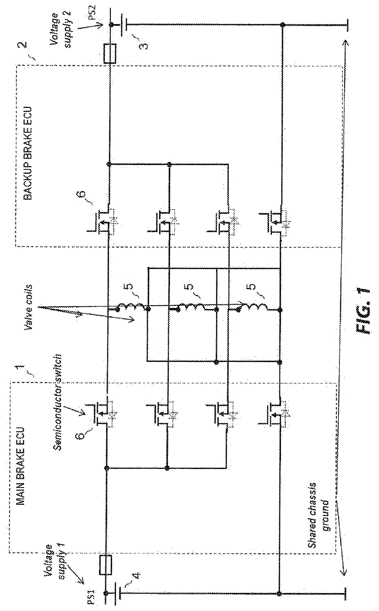
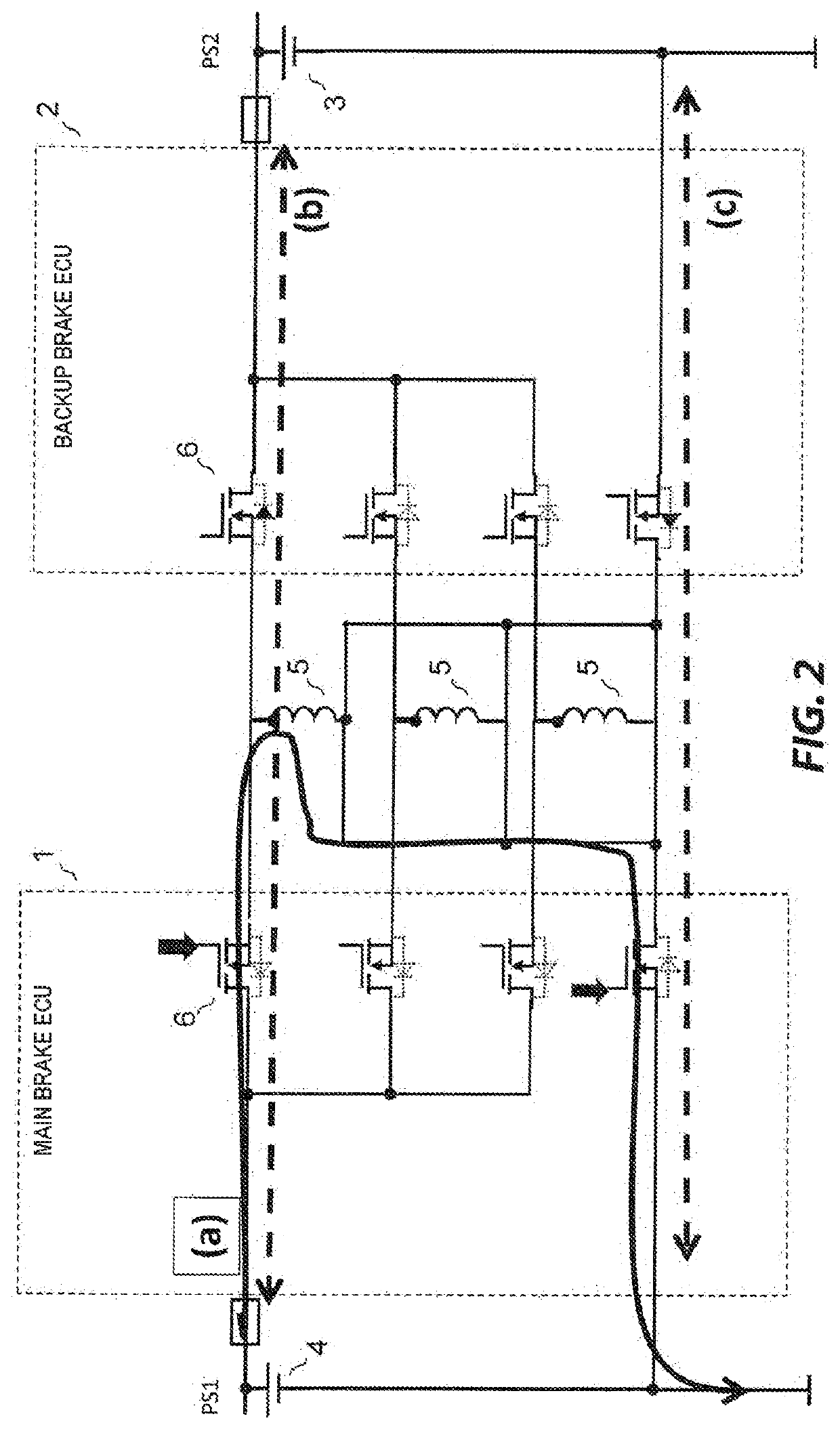
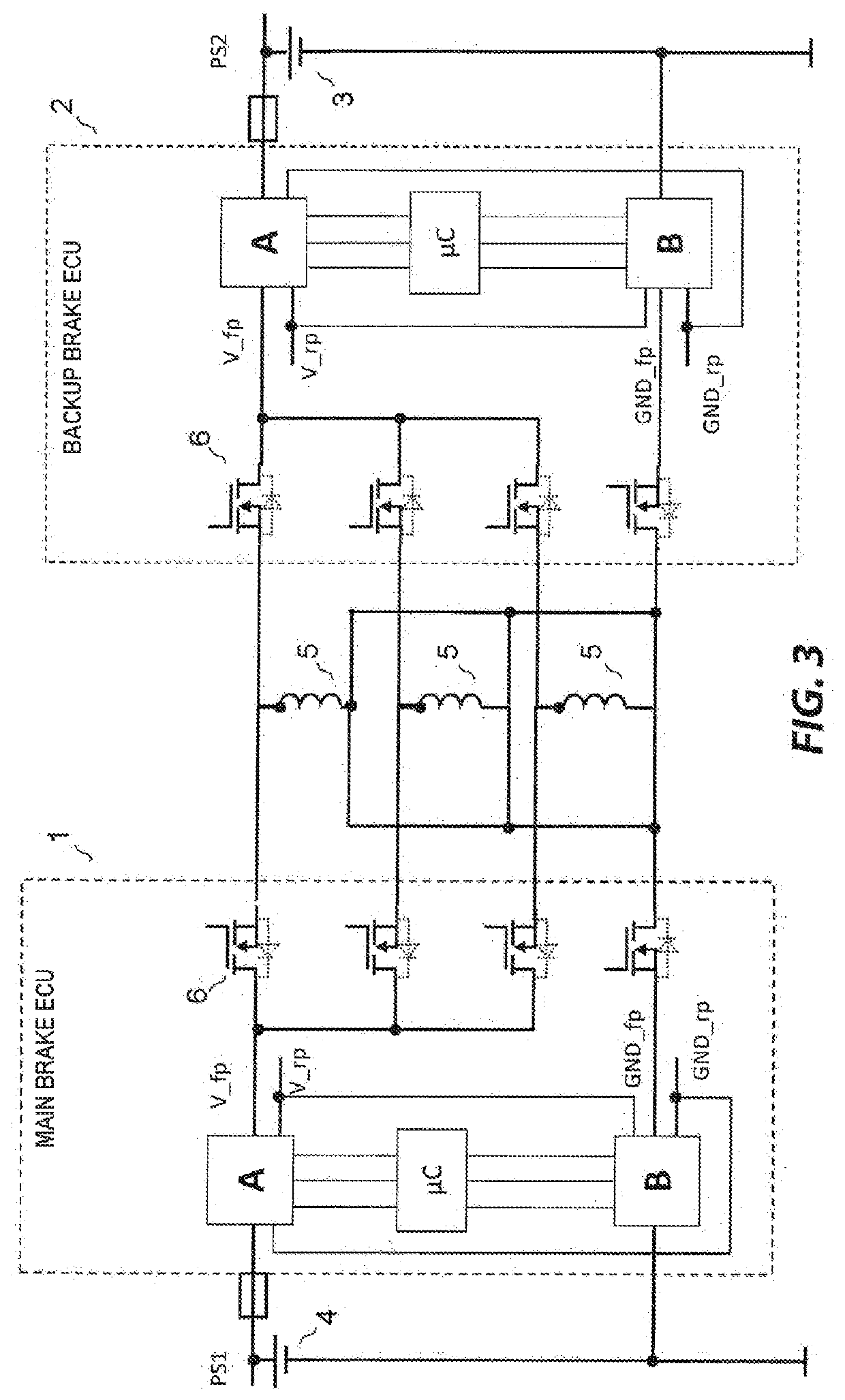
[0055]FIG. 1 shows a schematic structure of a part of a redundant air brake system for, for example, a vehicle having a plurality of control unit devices, here at least two control units and more precisely a main control unit (first control unit) 1 and a backup control unit (second control unit) 2, as well as a plurality, for example, a first, a second and a third, of solenoid valves 5 used jointly by the two control units 1, 2.

[0056]Each pin of the solenoid valves 5 is connected to both the main control unit 1 and the backup control unit 2. The main control unit 1 is supplied with a predetermined potential relative to a chassis ground by a first voltage supply 4, and the backup control unit 2 is supplied with the predetermined potential relative to the chassis ground by a second voltage supply 3. The main and backup control units 1, 2 are arranged and configured to switch switching devices 6, each located in the supply path and in the ground path, for example suitable MOSFETs or ot...

second exemplary embodiment

[0078]In a second exemplary embodiment, diodes are inexpensive and simple replacements for MOSFETs. The second exemplary embodiment can thus represent an embodiment that optimizes and simplifies the first exemplary embodiment. Replacing MOSFETs with diodes eliminates at least the need to measure voltage and current signals for monitoring and the control of each of the affected MOSFETs, resulting in less hardware and software overhead. In addition, and more cost-effectively and simply, at least one diode can be arranged externally to the control unit, i.e. outside a control unit or control device, for example, one integrated in a cable set or in an actuator such as a pressure control valve (PCV).

[0079]According to the second exemplary embodiment, diodes or functionally equivalent components or elements are arranged in electronic control units, in a wiring harness (for example, in plugs or plug sockets of pressure control valves or electronic control units) and / or in a special T-piece...


PUM


Abstract

A device for decoupling and / or protecting against compensation currents when at least one electric actuator is used jointly by a plurality of independently voltage-supplied control unit devices in redundant systems for autonomous driving. The electric actuator has, in each case, a common connection, via which the electric actuator can be coupled and switched to a common connection of other electrical actuators, and has at least one dedicated connection via which the at least one electric actuator can be individually supplied with current. A number of switching devices corresponding to the common connection and the number of dedicated connections of all the electric actuators is arranged to apply or not apply a switched current in the at least one electric actuator. Provided is at least one current flow blocking device configured to prevent an unwanted current flow to a non-active electronic control unit of the first and second control unit devices.

Description

FIELD OF THE INVENTION[0001]The present invention is based on a device for decoupling and protection from compensation currents in a redundant system for autonomous driving.BACKGROUND INFORMATION[0002]In highly automated or autonomously driven vehicles, such as highly automated or autonomously driven commercial vehicles, driver assistance systems instead of the driver control the vehicle and also monitor the vehicle's surroundings. Driver assistance systems are classified according to SAE in six levels (0 to 5). In particular in the case of vehicles which perform autonomous driving functions at least temporarily without a driver who is in a position to intervene at all times (in the case of assistance functions from level 3, which relates to highly automated driving, an underlying system assumes the longitudinal and transverse guidance in a specific application, detects system limits and prompts a driver to take over with sufficient time in reserve. The driver no longer needs to per...

Claims


Application Information

Patent Timeline
Patent Type & Authority Applications(United States)
IPC IPC(8): B60W50/02B60R16/023H02J9/06H02J7/00H02J1/10B60W50/023H02J7/14B60T17/22H02M3/07
CPCB60W50/0205H02J2310/40H02J9/06H02J7/0031H02J1/108B60W50/023H02J7/0034H02J7/1423B60T17/221B60T2270/413B60T2270/414H02M3/07B60T2270/415B60T2270/402B60R16/0231B60L2260/32B60L3/0092B60L3/0076B60R16/03
Inventor HOOS, FELIXBEYSE, THORSTENWINZ, DIETERSCHOLL, FRANKBECKER, KAI-SVENHERRMANN, GUENTERKAUFMANN, CHRISTIANRAMMERT, ALEXANDERBELLING, MICHAEL
Owner KNORR-BREMSE SYST FUER NUTZFAHRZEUGE GMBH
Why Eureka
Try Eureka