Protective device for decoupling electric control circuits in a redundant system for autonomous driving

a protection device and electric control technology, applied in brake control systems, brake systems, transportation and packaging, etc., can solve the problems of redundant configuration of critical electronic systems, inability to intervene and assume control of vehicles, and inability to detect faults in time,

Pending Publication Date: 2021-09-02
KNORR-BREMSE SYST FUER NUTZFAHRZEUGE GMBH
View PDF0 Cites 0 Cited by
  • Summary
  • Abstract
  • Description
  • Claims
  • Application Information

AI Technical Summary

Benefits of technology

[0015]Based on the above-mentioned set of problems, an object of the present invention is to prevent fault currents between voltage supplies via the control units in a compressed-air braking system with redundant control units jo

Problems solved by technology

However, in the event of a fault, for example a component failure, it may still be the case that the driver can no longer intervene and assume control of the vehicle, or at least no longer sufficiently quickly.
For safety reasons, critical electronic systems are therefore configured redundantly.
If a pressure control valve is controlled by two or more electronic control units, however, when one of the electronic control units applies test pulses to a magnet, the permanent monitoring in another electronic control unit would respond and incorrectly detect a fault.
In addition, if two electric circuits have a common ground (−), a ground offset between two controlling electronic control units can result in the destruction of one or both of the electronic control units.
Furthermore, a defective electronic control unit may be unintentionally supplied “backwards” if it has been disconnected from its supply voltage due to a fault, for example, or, if the faulty electronic control unit has a short circuit from its supply to ground, a current flowing to the solenoid fro

Method used


Image

  • Protective device for decoupling electric control circuits in a redundant system for autonomous driving
  • Protective device for decoupling electric control circuits in a redundant system for autonomous driving
  • Protective device for decoupling electric control circuits in a redundant system for autonomous driving

Examples


Embodiment Construction

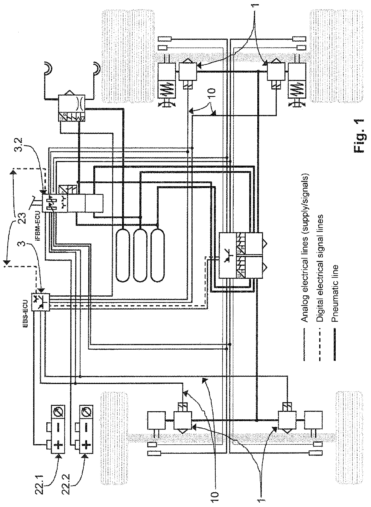
[0045]As described above, FIG. 1 shows schematically and in detail a structure of a known braking system or braking scheme, here with a first electronic control unit 3 as a first control unit or main control unit, and a second electronic control unit 3.2 as a control unit or backup control unit, as well as a plurality of pressure control valves or solenoid valves 1 used jointly by both control units 3, 3.2.

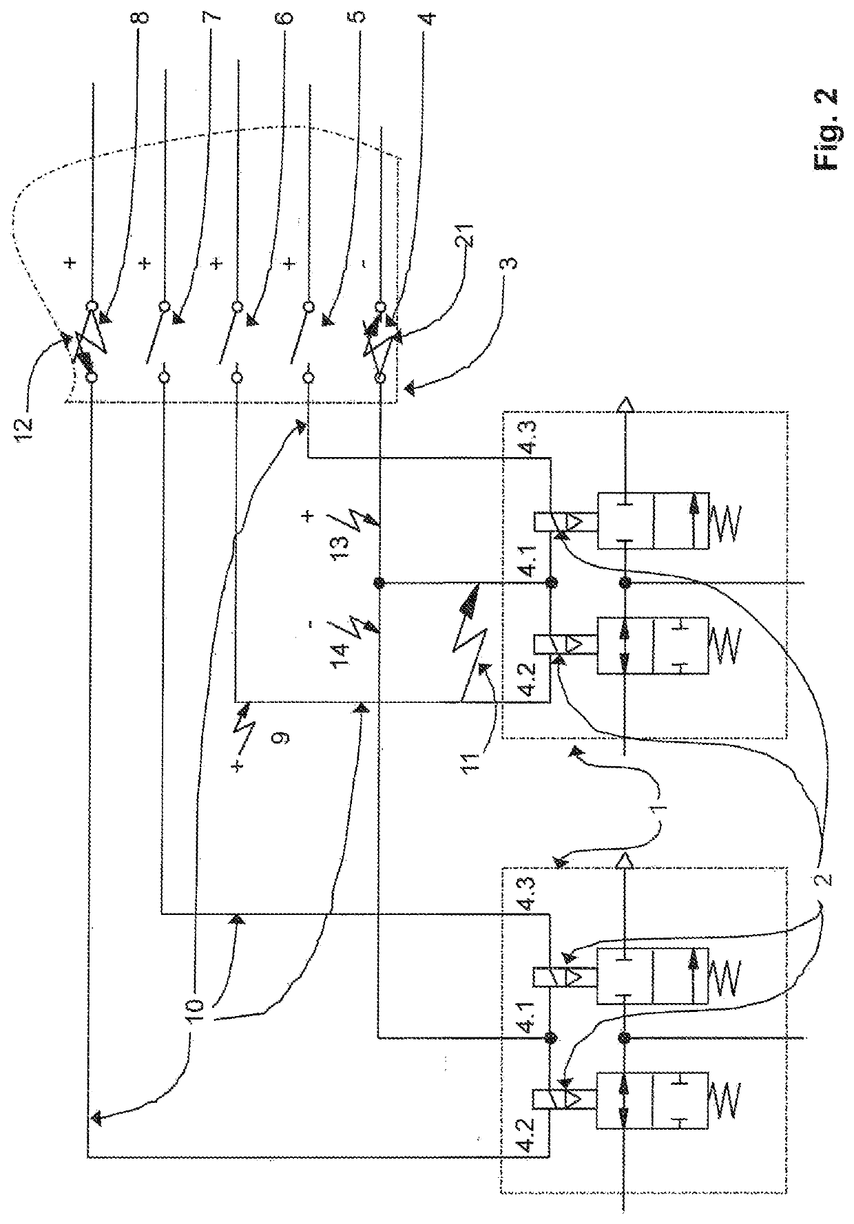
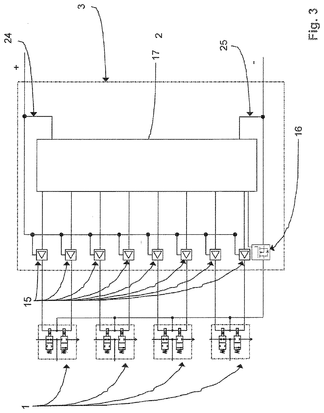
[0046]Each pin of the pressure control valves 1 is connected to both the main control unit 3 and the backup control unit 3.2. The main control unit 3 is supplied with a predetermined potential relative to a chassis ground by a first voltage supply 22.1, and the backup control unit 3.2 is supplied with the predetermined potential relative to the chassis ground by a second voltage supply 22.2. The main and backup control units 3, 3.2 are arranged and configured to switch switching devices 4, 5, 6, 7, 8, 16, each located in the supply path and in the ground path, for example suitable...


PUM


Abstract

A device for decoupling and/or protecting against compensation currents when at least one electropneumatic actuator is used jointly by a plurality of independently voltage-supplied control unit devices in redundant systems for autonomous driving. The electropneumatic actuator has, in each case, a common connection, via which the electropneumatic actuator can be coupled and switched to a common connection of other electropneumatic actuators, and has at least one dedicated connection via which the at least one electropneumatic actuator can be individually supplied with current. Switching devices, corresponding to the common connection and the number of dedicated connections of all the electropneumatic actuators, are arranged to apply or not apply a switched current in the at least one electropneumatic actuator. Provided is at least one current flow blocking device to prevent an unwanted current flow to a non-active electronic control unit of the first and second control unit devices.

Description

FIELD OF THE INVENTION[0001]The present invention is based on a protective device for decoupling electric control circuits in a redundant system for autonomous driving.BACKGROUND INFORMATION[0002]In highly automated or autonomously driven vehicles, such as commercial vehicles, driver assistance systems instead of the driver control the vehicle and also monitor the vehicle's surroundings. In particular in the case of vehicles which perform autonomous driving functions at least temporarily without a driver who is in a position to intervene at all times (assistance functions from level 3 of a total of six levels 1 to 6, which relates to highly automated driving), an underlying system assumes the longitudinal and transverse guidance in a specific application, detects system limits and prompts a driver to take over with sufficient time in reserve. The driver no longer needs to permanently monitor the vehicle or system, but potentially be able to take control), brake systems must still be...

Claims


Application Information

Patent Timeline
IPC IPC(8): B60W50/023B60T13/68B60T17/22
CPCB60W50/023B60T13/683B60W2510/18B60T2270/402B60T2270/413B60T17/221B60T17/22B60T13/68B60T2270/414B60W60/00
Inventor HERGES, MICHAELWOERNER, DIETERHECKER, FALK
Owner KNORR-BREMSE SYST FUER NUTZFAHRZEUGE GMBH
Why Eureka
Try Eureka