Electrophoretic display device with improved reflective luminance

a display device and display device technology, applied in static indicating devices, optics, instruments, etc., can solve the problem that epd devices sometimes experience the problem of low reflective luminance, and achieve the effect of improving reflective luminan

Active Publication Date: 2009-03-31
HYDIS TECH CO LTD
View PDF6 Cites 13 Cited by
  • Summary
  • Abstract
  • Description
  • Claims
  • Application Information

AI Technical Summary

Benefits of technology

[0008]Accordingly, the invention provides an electrophoretic display device having an improved reflective luminance. The invention also provides a method of driving such an electrophoretic display device.
[0008]Accordingly, the invention provides an electrophoretic display device having an improved reflective luminance. The invention also provides a method of driving such an electrophoretic display device.

Problems solved by technology

In addition, the EPD device is not a light-emitting device in itself, so it uses external light.
Due to the reliance on external light, EPD devices occasionally experience the problem of low reflective luminance.

Method used


Image

  • Electrophoretic display device with improved reflective luminance
  • Electrophoretic display device with improved reflective luminance
  • Electrophoretic display device with improved reflective luminance

Examples


first embodiment

[0020]Hereinafter, preferred embodiments will be described in detail with reference to the accompanying drawings. In the embodiments, like elements are denoted by like reference numerals. Elements that are referred to in the descriptions for different embodiments will be explained only in the first embodiment to minimize redundancy. In the drawings, the thickness and size of layers, films, and regions are exaggerated for clarity. It should be noted that, when an element such as a layer, film, region, or substrate is referred to as being “on” another element, it can be directly positioned on another element or intervening elements may be present.

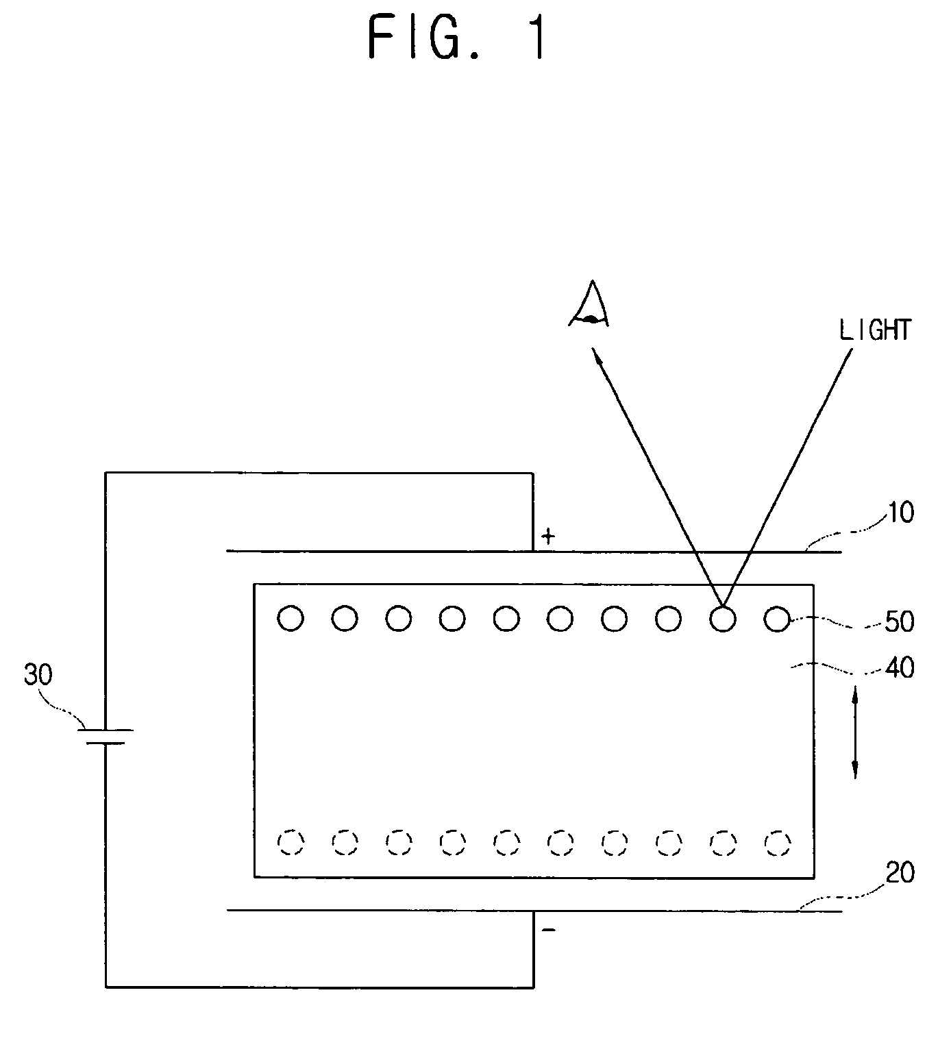
[0021]FIG. 1 is a schematic view showing the driving principle of an electrophoretic display device according to an embodiment of the invention.

[0022]As shown in FIG. 1, the electrophoretic display (EPD) device according to an embodiment of the invention includes a pair of electrodes 10 and 20 for forming an electric field. One of the electro...

third embodiment

[0072]FIG. 8 shows a pixel arrangement in the electrophoretic display panel according to the In this embodiment, four sub-pixels 170a, 170b, 170c and 170d that constitute one pixel 170 do not have the same area. For example, in the exemplary embodiment, the areas of the blue and white sub-pixels 170c and 170d are smaller than those of the red and green sub-pixels 170a and 170b. In other embodiments (not shown), the areas of the blue and white sub-pixels 170c and 170d may be larger than those of the red and green sub-pixels 170a and 170b.

fourth embodiment

[0073]FIG. 9 shows a pixel arrangement in the electrophoretic display panel according to the In this embodiment, six sub-pixels 170a1, 170a2, 170b, 170c1, 170c2 and 170d constitute one pixel 170. That is, one pixel 170 is constituted of two red sub-pixels 170a1 and 170a2, two blue sub-pixels 170c1 and 170c2, one green sub-pixel 170b, and one white sub-pixel 170d. In the embodiment shown, where the sub-pixels are arranged in a 3×2 matrix, the pixel 170 has a rectangular shape, not a square shape.


PUM

PropertyMeasurementUnit
reflectivityaaaaaaaaaa
dielectric constantaaaaaaaaaa
colorsaaaaaaaaaa

Abstract

An electrophoretic display device with an improved reflective luminance is presented. The electrophoretic display device includes an electrophoretic display panel including sub-pixels corresponding to four colors (e.g., red, green, blue, and white). A signal converter is provided for receiving an image signal for three colors and converting it into an image signal for four colors. A data driver is provided for supplying the converted image signal for four colors to the sub-pixels as a data voltage.

Description

[0001]This application claims priority to Korean Patent Application No. 2005-0063928 filed on Jul. 14, 2005 and all the benefits accruing therefrom under 35 U.S.C. §119, and the contents of the application in its entirety are herein incorporated by reference.BACKGROUND OF THE INVENTION[0002]1. Field of the Invention[0003]The present invention relates generally to an electrophoretic display device and more particularly to an electrophoretic display device in which sub-pixels exhibiting four different colors are used to improve reflective luminance.[0004]2. Description of the Related Art[0005]An electrophoretic display (EPD) device is a type of flat display device that is commonly used in electronic books. The EPD device includes two substrates with electric field formation electrodes formed therein and charged particles disposed between the two substrates. A voltage is applied to the two electrodes so that the charged particles move between the electrodes having opposite polarities, ...

Claims


Application Information

Patent Timeline
Patent Type & Authority Patents(United States)
IPC IPC(8): G02B26/00G09G3/34G02F1/167
CPCG02F1/133377G02F1/167G09G3/344G09G5/005G02F1/1362G02F2201/52G09G3/2074G09G5/006G09G2300/0452G09G2300/08G02F1/1685G02F1/1681G02F1/16766
Inventor KIM, JUN-HYUNGROH, NAM-SEOKPARK, DAE-JINCHOI, JEONG-YE
Owner HYDIS TECH CO LTD
Why Eureka
Try Eureka