Filling joint arrangement for a flowable filling medium

a filling joint and flowable technology, applied in the field of pivotable filling joint arrangement, can solve the problems of limited movement space and easily replaced, and achieve the effects of accurate selection, improved and stabilized guidance for joint portions, and precise abutment and additional guidance and stability

Inactive Publication Date: 2009-04-07
POLY CLIP SYST
View PDF18 Cites 3 Cited by
  • Summary
  • Abstract
  • Description
  • Claims
  • Application Information

AI Technical Summary

Benefits of technology

[0007]The present invention aims to overcome that disadvantage. A filling joint arrangement of the kind set forth in the opening part of this specification is provided that affords improved accessibility by virtue of a large pivotal angle.
[0020]A holding device which is provided on the filling arrangement and which supports the second filling pipe portion and / or the joint intermediate portion and / or pivots relative to the first filling pipe portion imparts the necessary stability to the filling arrangement and permits pivotal deflection movement of the second filling pipe portion by machine, from the filling position into the tilted end position.

Problems solved by technology

That affords a limited space for movement for pulling on sausage skin portions in a concertinaed-together configuration, particularly in the case of displacer members involving a large passage therethrough.
In addition, in contrast to fixedly inserted seals, it is easily replaceable when wear occurs.

Method used


Image

  • Filling joint arrangement for a flowable filling medium
  • Filling joint arrangement for a flowable filling medium
  • Filling joint arrangement for a flowable filling medium

Examples


Embodiment Construction

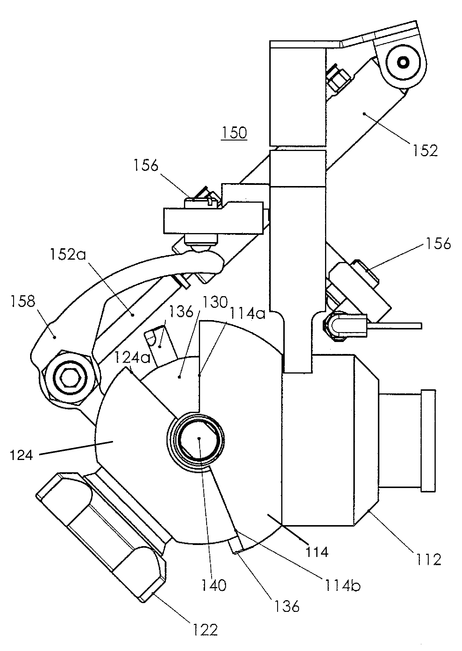
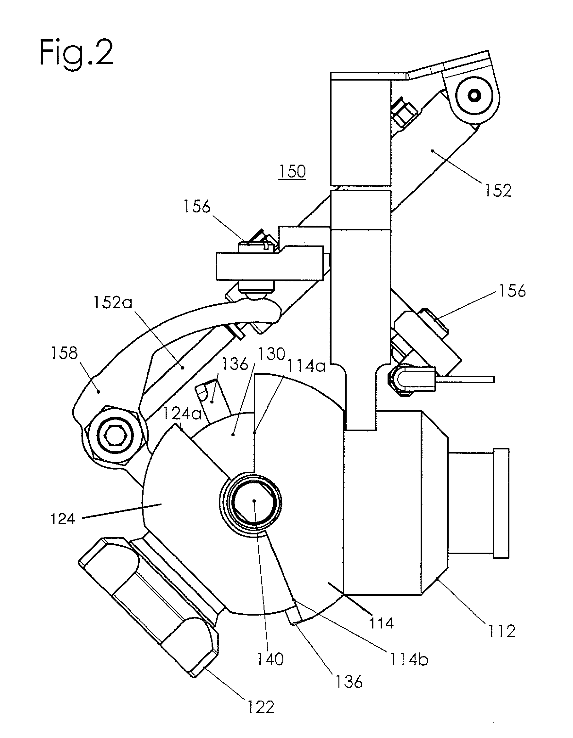
[0027]FIGS. 2 through 4 show a filling joint arrangement according to the invention. The filling joint arrangement includes a first filling pipe portion 110 of preferably stainless steel, which is connected to a filling machine (not shown). The structure further includes a second filling pipe portion 120 also preferably of stainless steel, which is connected to a packaging machine such as a sausage clipping machine (also not shown) which is arranged downstream of the filling machine in the production direction. The first and second filling pipe portions 110, 120 are each of a cross-section in the form of a circular ring with a respective longitudinal center line A, B which extend in mutually coaxial relationship in the filling position of the filling pipe portions 110, 120 (see FIG. 4).

[0028]At the end of the first filling pipe portion 110, which faces towards the second filling pipe portion 120, a first joint receiving portion 112 is arranged thereon while a second joint receiving ...


PUM


Abstract

A filling joint arrangement for a filling medium which is capable of flow, in particular for a sausage meat, including a first filling pipe portion with a first filling pipe axis and a second filling pipe portion with a second filling pipe axis, wherein the second filling pipe portion is reversibly pivotable from a filling position in which the second filling pipe axis is aligned with the first filling pipe axis into a tilted position in which the second filling pipe axis is out of alignment with the first filling pipe axis, and further including a joint device which is disposed in filling medium-tight relationship between the first and the second filling pipe portions and which has a first joint receiving portion connected in filling medium-tight relationship to the first filling pipe portion and which includes a joint intermediate portion which has a third filling pipe portion with a third filling pipe axis and which is held pivotably by the first joint receiving portion in such a way that it is reversibly pivotable from the filling position into a tilted position in which the third filling pipe axis is out of alignment with the first filling pipe axis. It is further provided that there is a second joint receiving portion which is connected in filling medium-tight relationship to the second filling pipe portion and which together with the second filling pipe portion is reversibly pivotable with respect to the joint intermediate portion out of the filling position by way of a tilted intermediate position in which at least the third filling pipe axis is out of alignment with the first filling pipe axis into a tilted end position in which the second filling pipe axis is out of alignment with the third filling pipe axis.

Description

BACKGROUND AND SUMMARY OF THE INVENTION[0001]The invention concerns a filling joint arrangement for a filling medium which is capable of flow, in particular a sausage meat, and more particularly to a pivotable filling joint arrangement.[0002]Disclosed is a filling joint arrangement which has a first filling pipe portion with a first filling pipe axis and a second filling pipe portion with a second filling pipe axis, wherein the second filling pipe portion is reversibly pivotable from a filling position in which the second filling pipe axis is aligned with the first filling pipe axis into a tilted position in which the second filling pipe axis is out of alignment with the first filling pipe axis. The filling arrangement further has a joint device which is disposed in filling medium-tight relationship between the first and the second filling pipe portions and which has a first joint receiving portion connected in filling medium-tight relationship to the first filling pipe portion and ...

Claims


Application Information

Patent Timeline
Patent Type & Authority Patents(United States)
IPC IPC(8): A22C11/00
CPCA22C11/0209
Inventor WALDSTADT, MANFRED
Owner POLY CLIP SYST
Why Eureka
Try Eureka