Apparatus for delivering pressurized fluid

a technology of pressurized fluid and apparatus, which is applied in the storage of respirators, oxygen respirators, life-saving devices, etc., can solve the problems of liquidized gas storage and fluid loss, and achieve the effect of increasing the available fluid

Inactive Publication Date: 2009-04-14
PACIFIC CONSOL INDS
View PDF17 Cites 4 Cited by
  • Summary
  • Abstract
  • Description
  • Claims
  • Application Information

AI Technical Summary

Benefits of technology

[0009]Another aspect of at least one of the inventions disclosed herein includes the realization that in transporting a compressed fluid, it can be difficult to stock pile and transfer large numbers of compressed fluid vessels because such vessels are typically cylinder-shaped. For example, by housing at least one compressed fluid vessel in a container which includes projections and recesses configured to be nestable with each other, the housings can be stock piled or stacked conveniently in a stable manner. This further simplifies storing and transporting such fluid vessels.
[0010]Thus, in accordance with yet another aspect of at least one of the inventions disclosed herein, a compressed fluid housing assembly comprises a housing and at least one pressure vessel disposed therein. The housing includes a fluid outlet port disposed on an outer surface of the housing. Additionally, the housing includes projections and recesses that are sized so as to be nestable with each other. Thus, when a plurality of the housings are stacked, the projections and recesses nest with each other, thereby forming a more stable stack. This is particularly advantageous where such housings are transported in aircraft or other large vehicles, such as those commonly used in military operations.
[0011]Further aspects of at least one of the inventions disclosed herein includes the realization that where fluid ports are disposed on an outer surface of a housing containing pressurized fluid vessels, the ports can be damaged during transportation. Thus, in accordance with another aspect of at least one of the inventions disclosed herein, a fluid delivery assembly comprises a housing and a pressure vessel disposed therein. The housing includes at least one fluid outlet port disposed on the outer surface of the housing. The outer surface of the housing defines an outer peripheral contour. The outlet port is disposed in a recess such that the outlet port is recessed from the outer contour of the housing. As such, the outlet port is protected from impact or contact with other bodies.
[0014]As such, the user of such fluid delivery units has more flexibility in deciding how to stock pile the units. For example, having status indicators on two sides of the housing allows the user to choose between several alternatives for stacking the units so that at least one of the status indicator is visible when the units are stacked.
[0015]Another aspect of at least one of the inventions disclosed herein is that although storage of pressurized fluids in a gaseous state is less volumetrically efficient, certain pressurized gases can be stored more economically in a gaseous state, due to the elimination of losses associated with the storage of liquidized fluids.
[0017]However, with the development of lightweight, high pressure vessels, large quantities of pressurized gaseous fluids, such as oxygen, can be stored indefinitely, with near zero loss, in a package that is comparable to the size and weight of a liquid oxygen container holding the same mass of oxygen. Thus, in accordance with yet another aspect of at least one of the inventions disclosed herein, a container for pressurized gaseous oxygen comprises a housing, at least one lightweight pressure vessel disposed in the housing. The pressure vessel is configured to store pressurized gaseous oxygen at a pressure of at least about 3,000 psi.

Problems solved by technology

However, the storage of liquidized gases presents certain difficulties.
The venting of such gas presents a loss of the fluid.

Method used


Image

  • Apparatus for delivering pressurized fluid
  • Apparatus for delivering pressurized fluid
  • Apparatus for delivering pressurized fluid

Examples


Embodiment Construction

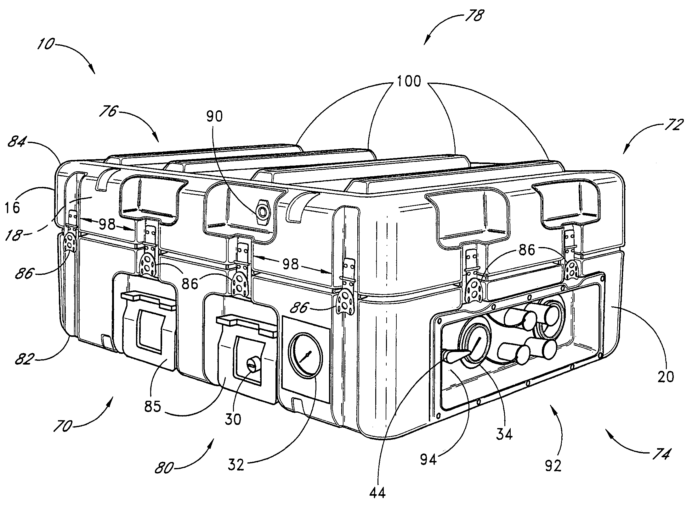
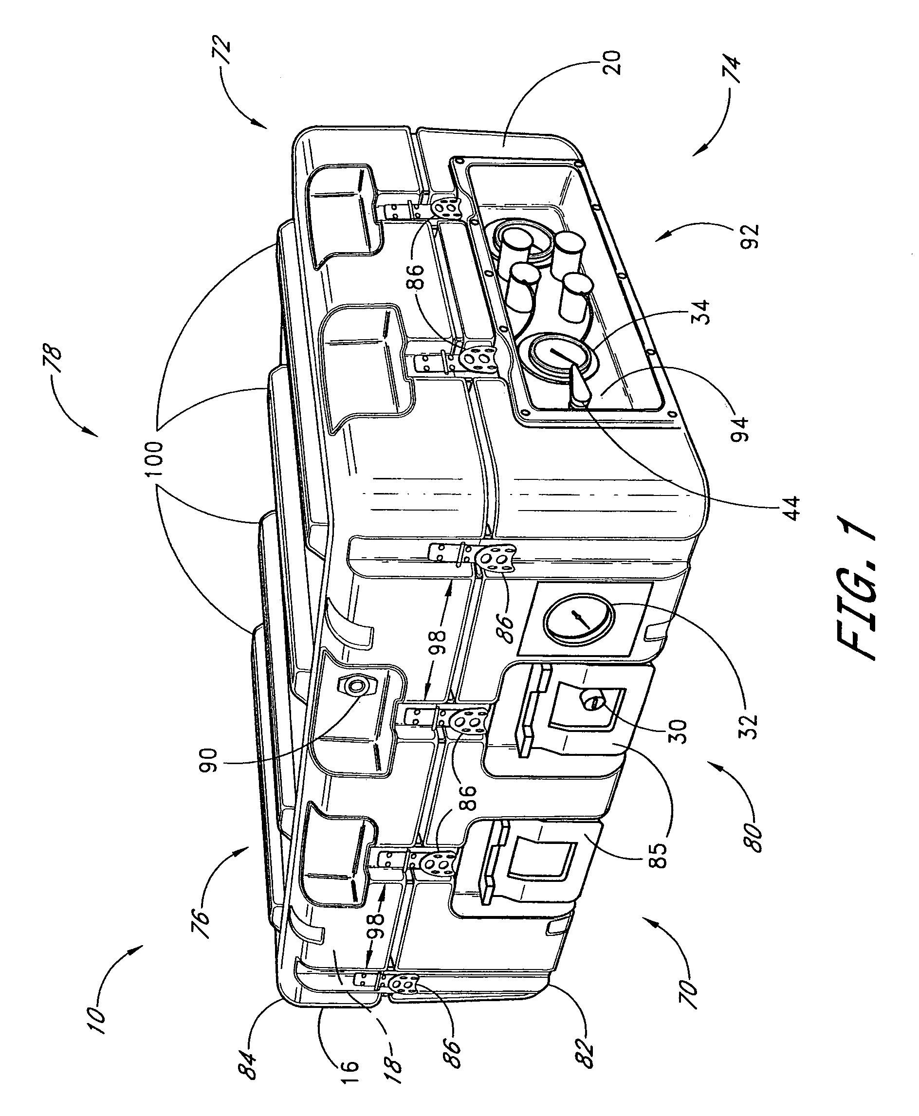
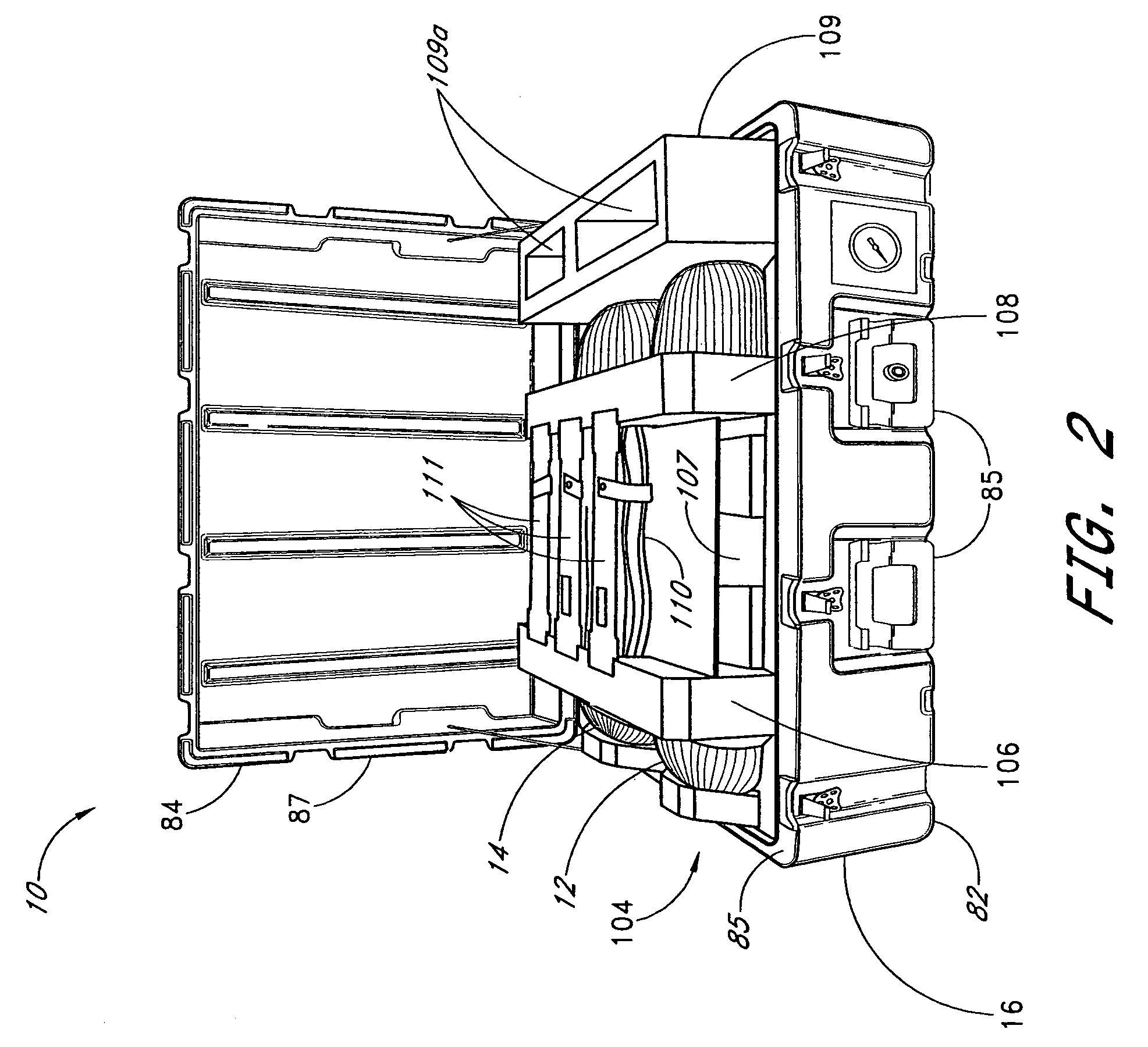
[0032]With initial reference to FIGS. 1 and 2, a container 10 is illustrated therein. The container 10 is configured to enclose at least one pressure vessel, such as the pressure vessels 12 and 14 (FIG. 2). The container 10 includes a body 16 that defines an internal cavity 18 for containing the pressure vessels 12, 14. The body 16 also defines an outer surface 20 of the container 10. The outer surface 20 includes a plurality of recesses, described in greater detail below, for protecting certain devices disposed on the outer surface 20. The body can be constructed with any material. For example, but without limitation, the body 16 can be formed of metals, plastics, or composites. Preferably, the body 16 of the container 10 defines at least a substantially waterproof barrier for the internal volume 18. Further details of the body 16 are described below.

[0033]The pressure vessels 12, 14 can be of any known design. Preferably, the pressure vessels 12, 14 are in the form of light-weight...


PUM


Abstract

A container for enclosing at least one pressure vessel includes interface devices accessible on an exterior of the outer surface of the container. The container can also include various features for enhanced efficiency and convenience in stock piling of such containers.

Description

RELATED APPLICATION[0001]This application is a Divisional of U.S. application Ser. No. 10 / 439,368, filed May 16, 2003 now U.S. Pat. No. 7,028,553, which is incorporated herein by reference.BACKGROUND OF THE INVENTION[0002]1. Field of the Invention[0003]The present application is directed to methods and devices for delivering pressurized fluids, and in particular, containers for enclosing pressurized fluid vessels.[0004]2. Description of the Related Art[0005]In the art of transporting pressurized fluids, it has long been known that a high level of volumetric efficiency is achieved where fluids are compressed into a liquid state. However, the storage of liquidized gases presents certain difficulties. For example, many fluids which are gasses at atmospheric conditions, require cryogenic storage conditions. As soon as such a liquidized fluid is removed from the cryogenic environment, it will continuously boil, thereby converting the liquid into gas. As such, the pressure within the vess...

Claims


Application Information

Patent Timeline
Patent Type & Authority Patents(United States)
IPC IPC(8): A61M15/00A62B25/00
CPCA62B25/00
Inventor SMITH, LEEZARATE, ROBERT A.
Owner PACIFIC CONSOL INDS
Why Eureka
Try Eureka