
Thermally Conductive Composition

Active Publication Date: 2020-01-16
SEIKO EPSON CORP +1
View PDF0 Cites 0 Cited by
  • Summary
  • Abstract
  • Description
  • Claims
  • Application Information

AI Technical Summary

Benefits of technology

The present invention is about a thermally conductive composition that can reduce electromagnetic waves of different frequencies. The composition has a high relative permeability, which can reduce the electromagnetic waves in the high-frequency range. It also has a low relative permittivity, which can reduce the transfer of electromagnetic waves from electronic components to heat dissipation devices. Therefore, the invention can reduce electromagnetic waves regardless of the frequency range. This makes it useful in electronic components that generate large amounts of heat and need to be cooled effectively.

Problems solved by technology

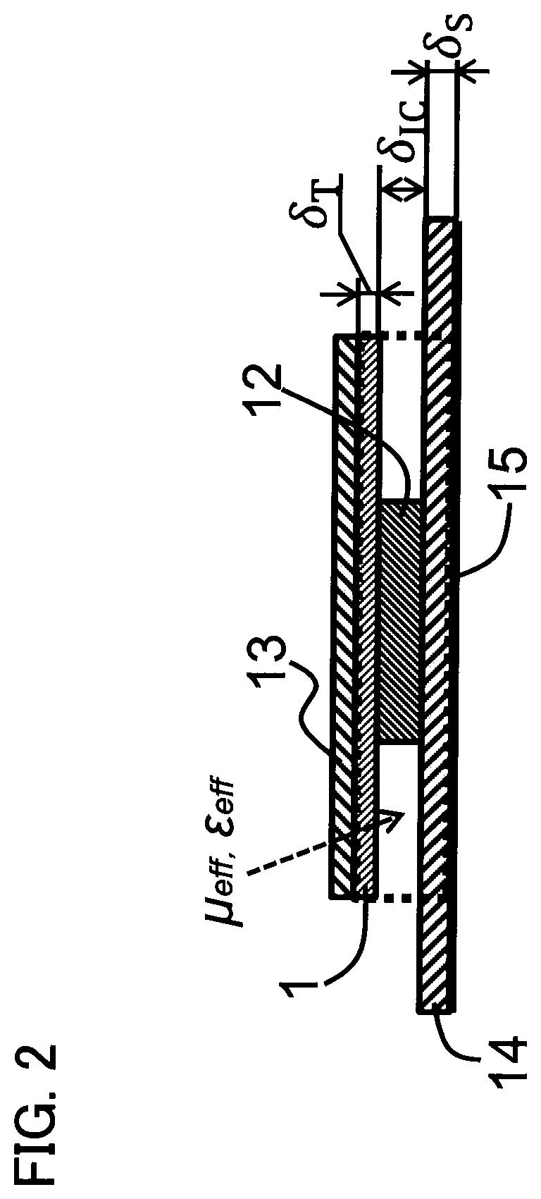
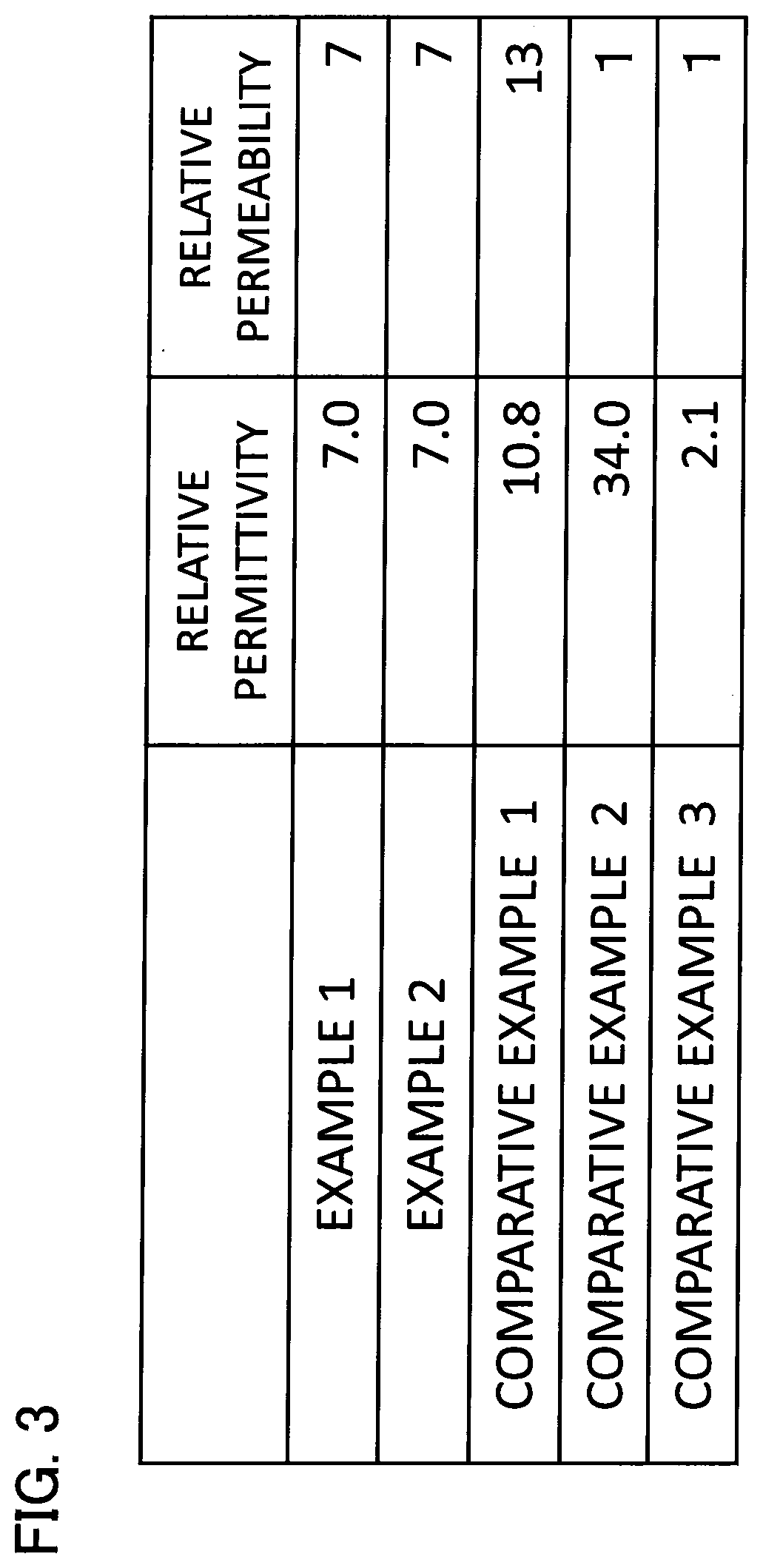
Further, the reduction of the relative permittivity of the entire thermally conductive composition to a value as low as 7 or lower makes it possible that by sandwiching the thermally conductive composition between an electronic component such as IC or the like and a heat dissipation device such as heat sink or the like, the electrostatic capacitance between the electronic component such as IC or the like and the heat dissipation device is reduced, making it difficult to transfer the electromagnetic wave emitted from the electronic component such as IC or the like to the heat dissipation device.

Method used


Image

  • Thermally Conductive Composition
  • Thermally Conductive Composition
  • Thermally Conductive Composition

Examples


example 1

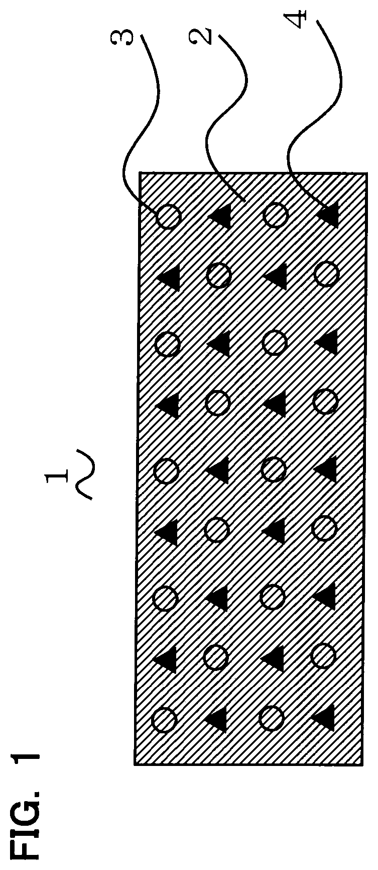
[0042]General-use acrylic polymer was used as the base material 2 of the thermally conductive sheet 1 of Example 1. Further, perlite balloon was used as the permittivity adjusting filler 3, and two kinds of Ni—Zn soft ferrites with different particle sizes were used as the high permeability filler 4. The mixing ratio of each filler to the base material 2 was such that the mixing ratio of acrylic polymer was about 14 wt %, and that of perlite balloon was about 6 wt %, while that of the Ni—Zn soft ferrite with the larger particle size was about 27 wt %, and that of the Ni—Zn soft ferrite with the smaller particle size was about 53 wt %. To the thermally conductive sheet 1, furthermore, additives such as an antioxidant, a crosslinking agent, a multifunctional monomer and so on were added. The mixing ratio of each additive to the base material 2 was such that the mixing ratio of the antioxidant was about 0.05 wt %, and that of the crosslinking agent was about 0.14 wt % while that of the...

example 2

[0043]General-use acrylic polymer was used as the base material 2 of the thermally conductive sheet 1 of Example 2. Further, acrylic group balloon (product name: “Expancel 920 DE 40 d30” made by Akzo Nobel Pulp and Performance Chemicals AB), which is a kind of organic balloon, was used as the permittivity adjusting filler 3, and two kinds of Ni—Zn soft ferrites with different particle sizes were used as the high permeability filler 4. Further, to the thermally conductive sheet 1, inexpensive aluminum hydroxide was added as a thermally conductive filler, and magnesium hydroxide serving to increase the viscosity was added as a viscosity adjusting filler. The mixing ratio of each filler to the base material 2 was such that the mixing ratio of acrylic polymer was about 11 wt %, that of aluminum hydroxide was about 4 wt %, that of magnesium hydroxide was about 3 wt %, and that of acrylic group balloon was about 0.3 wt %, while that of the Ni—Zn soft ferrite with the larger particle size ...

modified examples

[0070]It is to be noted that the present invention is not limited to the above-described embodiment, and various modifications are possible within the spirit and scope of the present invention. Modified examples of the present invention will be described below.


PUM

PropertyMeasurementUnit
Electrical conductoraaaaaaaaaa
Permeabilityaaaaaaaaaa
Thermal conductivityaaaaaaaaaa

Abstract

A thermally conductive composition is provided, which comprises: a base material; and at least one of a permittivity adjusting filler having a lower permittivity than the base material and a high permeability filler having a higher permeability than the base material. The entire thermally conductive composition has a relative permeability higher than 1 and a relative permittivity of 7 or lower.

Description

CROSS-REFERENCE TO RELATED APPLICATION[0001]This application is based on and claims the benefit of priority of the prior Japanese Patent Application No. 2018-131901, filed on Jul. 11, 2018, the entire contents of which are incorporated herein by reference.BACKGROUND OF THE INVENTION1. Field of the Invention[0002]The present invention relates to a thermally conductive composition to promote heat dissipation from a heat source such as an electronic component.2. Description of the Related Art[0003]Conventionally, thermally conductive compositions such as thermally conductive sheets with superior thermal conductive properties have been manufactured. For example, a thermally conductive composition such as a thermally conductive sheet is sandwiched between a heat source such as an electronic component or the like and a heat dissipation device such as a heat sink or the like, and is used to efficiently transfer and release heat (dissipate heat) from the heat source to the heat dissipation ...

Claims


Application Information

Patent Timeline
IPC IPC(8): H05K9/00C08K3/36C08K3/013
CPCC08K2003/385C08K3/013C08K3/36H05K9/0088C08L33/10C08K2201/001H01L23/3737H01L23/3733H05K9/0083H01L23/552H01L23/42C09K5/14H01F1/37
Inventor MATSUZAKI, TORUKAWAGUCHI, YASUHIROSAITO, MASAHIROMITSUYA, KENSUKEITO, MASAAKIOMORI, TOSHIYUKI
Owner SEIKO EPSON CORP
Learn More