Road-rail dual-purpose vehicle

Pending Publication Date: 2020-12-31
CRRC YANGTZE CO LTD
View PDF0 Cites 2 Cited by
  • Summary
  • Abstract
  • Description
  • Claims
  • Application Information

AI Technical Summary

Benefits of technology

The present disclosure relates to a road-rail dual-purpose vehicle that can easily transfer between rail and road transportation without the need for other apparatus. The vehicle has a single-axle bogie with a large stroke, making it easy to lift off a rail surface. The suspension system is designed for lifting and mounting at a hardened road bed. The vehicle also has a bearing bolster that connects to the vehicle frame and the single-axle bogie, as well as a secondary load-bearing airbag in the longitudinal beam to increase the suspension stroke. The impact seat assembly is designed with a U-shaped impact seat body and a coupler draft gear supporting beam for easy installation and disassembly of the coupler draft gear. The technical effects of the invention are that it reduces transfer time, simplifies road-rail transfer at railway stations, and makes the vehicle structure more compact.

Problems solved by technology

1. When changing from road transportation to railway transportation, it is necessary to provide a primary traction-bolster arrangement, a secondary traction-bolster arrangement and a bogie. When changing from railway transportation to road transportation, it is necessary to remove the primary traction-bolster arrangement, the secondary traction-bolster arrangement and the bogie, which greatly increases transfer time.
2. A transfer between a road transportation mode and a railway transportation mode of the road-rail dual-purpose vehicle needs to be carried out in a dedicated site, and a forklift for carrying the bogie is needed correspondingly; the transfer site must have a hardened road bed suitable for the length of the road-rail dual-purpose vehicle, and a surface of the hardened road bed must have a same height as a track surface and be transited easily to the ground; moreover, the railway stations participating in road-to-rail transfer need to set up a dedicated storage site for the traction-bolster arrangement with bogies. Thus, the number of railway stations used for road-rail transfer will be greatly limited.

Method used


Image

  • Road-rail dual-purpose vehicle
  • Road-rail dual-purpose vehicle
  • Road-rail dual-purpose vehicle

Examples


Embodiment Construction

[0076]In order to make the objectives, technical solutions and advantages of present disclosure clearer, embodiments of present disclosure will be described in detail with reference to accompanying drawings.

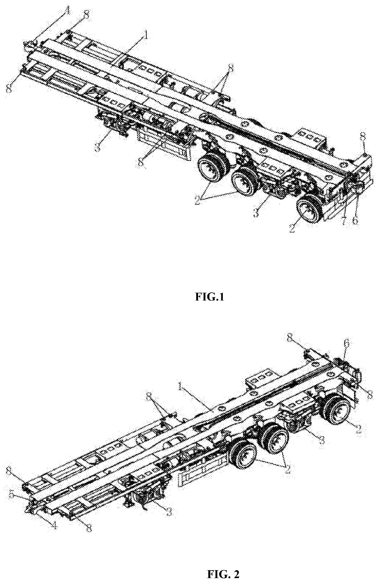
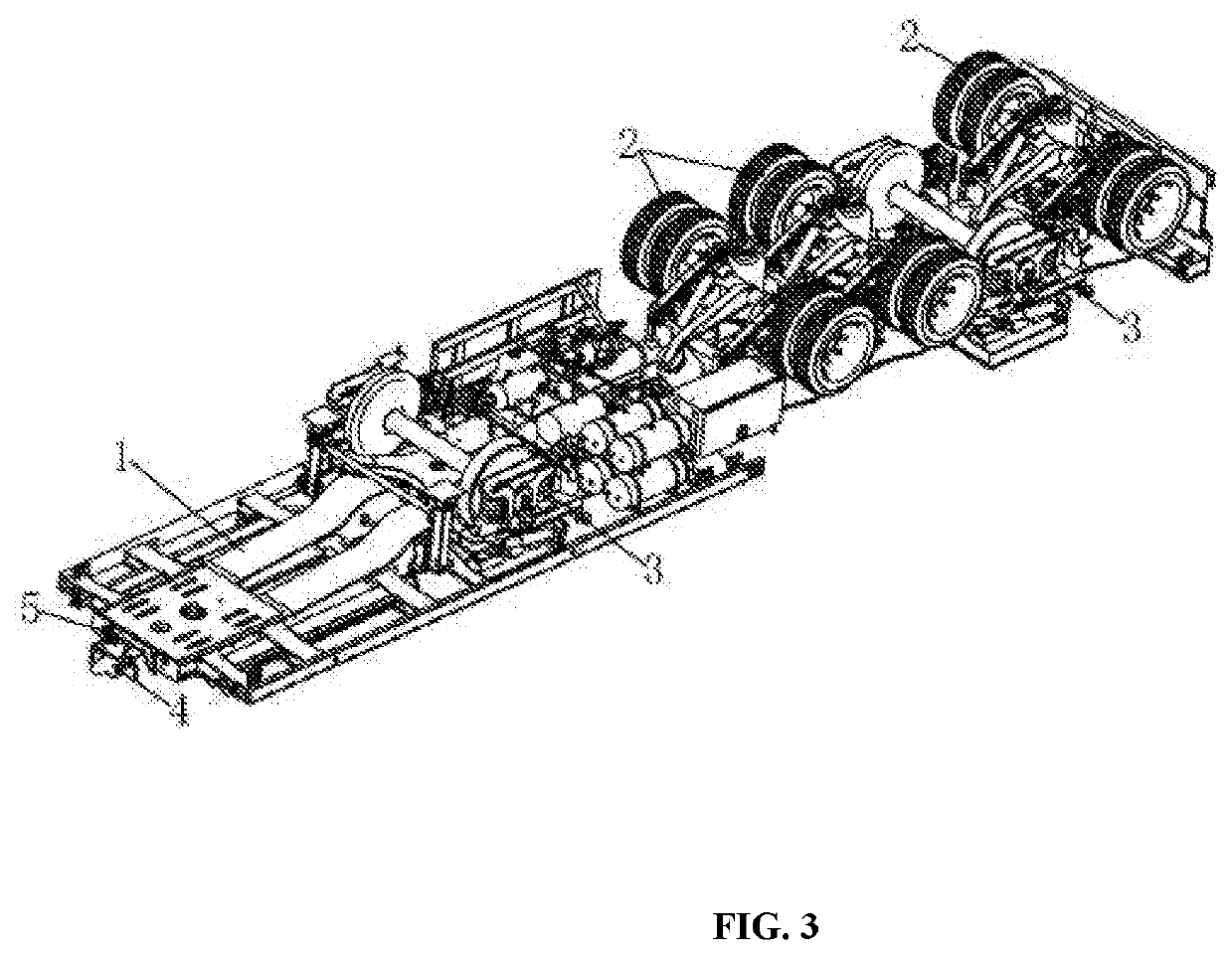
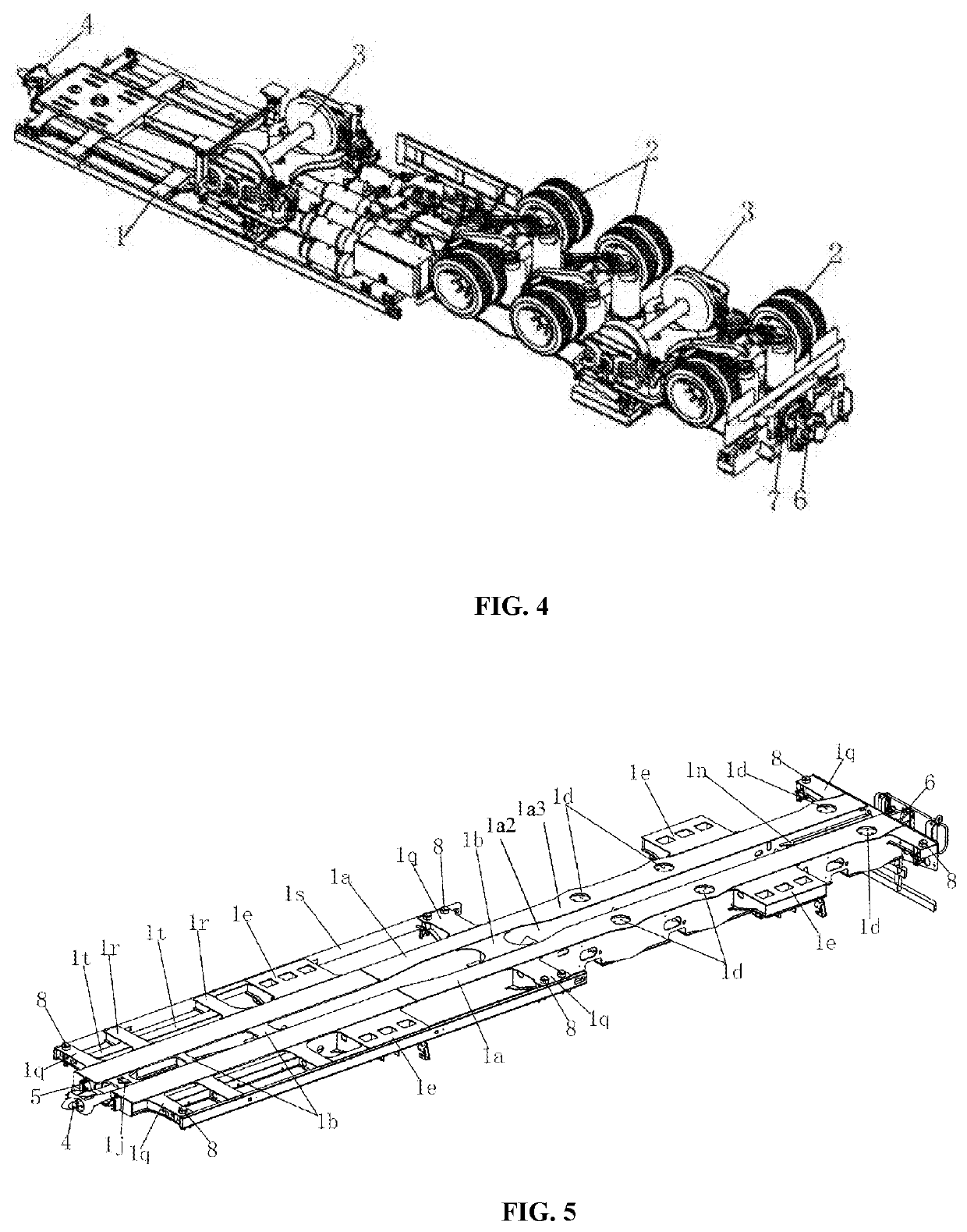
[0077]As shown in FIGS. 1 to 35, a road-rail dual-purpose vehicle according to one or more embodiments of the present disclosure comprises a vehicle frame 1, a suspension 2 and a single-axle bogie 3. The vehicle frame 1 comprises two longitudinal beams 1a arranged in parallel with each other, and the two longitudinal beams 1a are connected by a longitudinal beam connection plate 1b. A lifting airbag mounting seat 1c is provided between the two longitudinal beams 1a; a load-bearing airbag insertion hole is formed in a lower cover plate 1a1 of the longitudinal beam 1a at a position corresponding to the lifting airbag mounting seat 1c, and a load-bearing airbag mounting seat 1d is installed in the load-bearing airbag insertion hole. A bearing bolster 1e is installed on an outer side...


PUM


Abstract

The present disclosure discloses a road-rail dual-purpose vehicle, comprising a vehicle frame (1), and a lifting airbag mounting seat (1c) is provided between two longitudinal beams (1a) of the vehicle frame (1); a load-bearing airbag insertion hole is formed in a lower cover plate (1a1) of the longitudinal beam (1a); a load-bearing airbag mounting seat (1d) is installed in the load-bearing airbag insertion hole, and a bearing bolster (1e) is installed on an outer side of the longitudinal beam (1a). A suspension (2) comprises an axle assembly (2a); a lifting airbag (2b) is installed in a middle portion of a front end of the axle assembly (2a); both sides of the rear end of the axle assembly (2a) are provided with primary load-bearing airbags (2c); and the two primary load-bearing airbags (2c) are respectively provided with the secondary load-bearing airbags (2c); the lifting airbag (2b) is installed on the lifting airbag mounting seat (1c), and the secondary load-bearing airbag (2e) is installed in the load-bearing airbag mounting seat (1d). The single-axle bogie (3) comprises a framework (3a), and both ends of the framework (3a) are provided with axle boxes (3b); a primary damping spring assembly (3d) is provided between the axle boxes (3b) and the vehicle frame (1); and a vehicle frame connection assembly (3f) is provided on both ends of the top surface of the framework (3a) respectively; the framework (3a) is installed on the bottom surface of the bearing bolster (1e) through the vehicle frame connection assembly (3f). The road-rail dual-purpose vehicle is suitable for transportation.

Description

CROSS REFERENCES TO RELATED APPLICATIONS[0001]This application claims the priorities of Chinese Patent Application No. 201810846327.9, filed with the China Patent Office on Jul. 27, 2018, and Chinese Patent Application No. 201821211150.7, filed with the China Patent Office on Jul. 27, 2018, each of which is incorporated herein by reference in its entirety.TECHNICAL FIELD[0002]The present disclosure relates to the technical field of road transportation, and in particular to a road-rail dual-purpose vehicle.BACKGROUND OF THE PRESENT DISCLOSURE[0003]With the development of transportation capacity, cargo owners have increasingly higher requirements for the timeliness of delivery of goods. Countries are continuously putting effort to increase speed of goods delivery by rail, striving to achieve an advantage in speed of goods delivery, and gradually forming a “door to door” transportation represented by container transportation.[0004]At present, one of the main ways to realize “door-to-do...

Claims


Application Information

Patent Timeline
IPC IPC(8): B60F1/04
CPCB60F1/046B60F1/04B60F1/00B60F1/005B60F1/02B60F1/043B61D3/16
Inventor HU, HAIPINGLUO, HUILIU, DANYANJIANG, RUIJINLIU, FENGWEILI, ZIMINGPENG, XIANHONGYAO, XIONGXIANG, ZHIYINGWU, XIANNIANHUANG, CHUNYU
Owner CRRC YANGTZE CO LTD
Why Eureka
Try Eureka