Ring-type tensioner

a tensioner and ring technology, applied in the field of tensioners, can solve the problems of excessive tension in the chain, excessive wear, and instability in the control of chain tension, and achieve the effect of preventing expansion and facilitating assembly and maintenance of the tensioner

Active Publication Date: 2014-06-03
TSUBAKIMOTO CHAIN CO
View PDF39 Cites 2 Cited by
  • Summary
  • Abstract
  • Description
  • Claims
  • Application Information

AI Technical Summary

Benefits of technology

[0013]The profile of the radial wall of the groove can also be straight in the same axial plane so that the radial ring surface can come into face-to-face area contact with the radial wall surface of the groove. The straight profiles of the ring surfaces help to prevent bit-locking caused by wear of the ring by reducing contact pressure. Avoidance of bit-locking is enhanced when the radial walls of the groove in the plunger-accommodating hole also have straight profiles.
[0025]According to still another aspect of the invention, the manipulable parts of the ring are located on the ring so that they are separated from each other circumferentially by a gap when the ring is in engagement with a groove of the plunger and the ring diameter retaining tool is not retaining the manipulable parts in fixed relation to each other. The ring-diameter retaining tool includes a part insertable into the gap when the tool is not retaining the manipulable parts in fixed relation to each other. The thickness of the insertable part of the tool is larger than the gap, and sufficiently large to expand the ring to a diameter greater than the maximum diameter of the plunger at the locations of the grooves. Therefore, by insertion of the insertable part of the tool into the gap, the plunger can be released from the ring and allowed to move axially in the plunger-accommodating hole. Accordingly, it is possible to facilitate assembly and maintenance of the tensioner.

Problems solved by technology

Line contact causes high contact pressure, resulting in excessive wear.
Wear of the elastic ring, in turn, can result in instability in the control of chain tension, and in a condition in which the ring is caught between the plunger and the housing, a phenomenon known as “bit-locking.”
If the plunger protrudes excessively, due to thermal contraction of the engine or to thermal expansion of the chain, excessive tension can be generated in the chain.
If air enters the oil chamber of the tensioner while the engine is stopped, the hydraulic pressure in the oil chamber can become incapable of preventing retraction of the plunger.
Therefore, when the engine is started, excessive setback movement of the plunger in reaction to the force applied to the plunger by the chain can result in the generation of a flapping noise in by the chain.
Manual expansion is difficult to carry out smoothly because, it is necessary for an individual to use fingers to hold both ends of the elastic ring.

Method used


Image

  • Ring-type tensioner
  • Ring-type tensioner
  • Ring-type tensioner

Examples


first embodiment

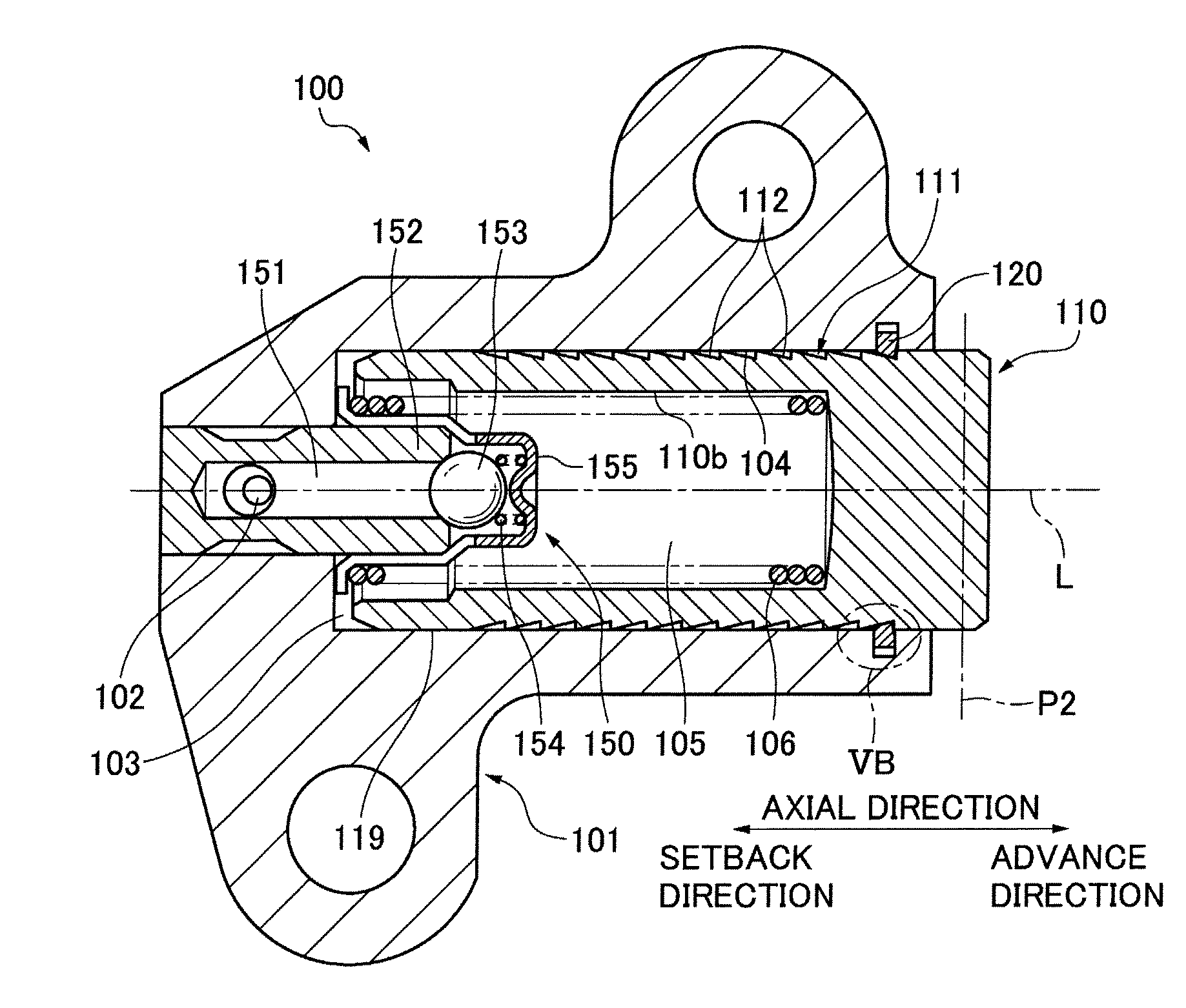
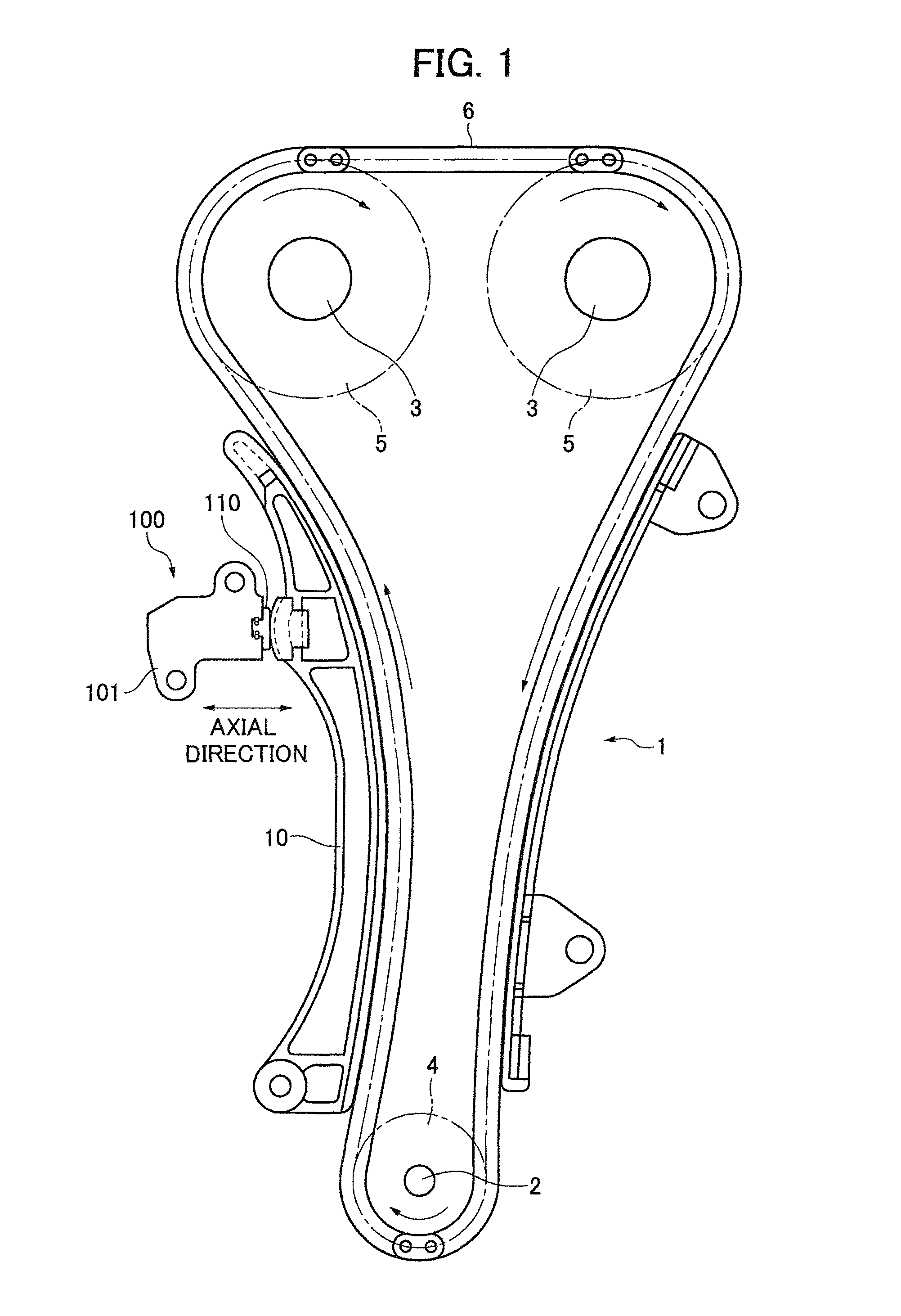
[0046]As shown in FIG. 1, a ring-type tensioner 100 according to the invention is provided in a timing chain transmission 1 of a DOHC (dual overhead cam) internal combustion engine (not shown). The timing chain transmission 1 comprises a driving sprocket 4 rotatably driven by an engine crankshaft 2, a pair of driven sprockets 5 respectively fixed to a pair of camshafts 3, and an endless timing chain 6 in mesh with teeth of sprockets 4 and 5.

[0047]The tensioner 100 is mounted on the engine on the slack side of the chain 6, i.e., adjacent the span of the chain that travels from the crankshaft sprocket 4 toward one of the camshaft sprockets 5. The tensioner comprises a housing 101 and a plunger 110 that is movable in an axial direction in and out of the housing 101 to apply tension to the chain 6 through a pivoted lever 10 supported on the engine. The plunger 110 presses against the lever 10 at a location remote from the lever's pivot axis, maintaining tension in the chain, but is mova...

second embodiment

[0084]In the invention, shown in FIGS. 10 through 14, a rack 211 composed of grooves 212 (FIG. 12) extends axially along a part of the outer circumferential surface 110a of a plunger 110 in a ring-type tensioner 200. The grooves 212 are straight, parallel grooves extend parallel to a plane P2 (FIG. 10) orthogonal to the axis L (FIG. 13A) of the plunger and the plunger-accommodating hole.

[0085]As shown in FIG. 13B, in this embodiment, the angle 02 of the forward-facing inclined surface 123 of the ring is equal to the angle θ1 of the rearward-facing surface 113 of the groove 112 in the plunger. Likewise, the angle ∝2 of the rearward-facing surface of the ring is equal to angle ∝1 of the forward facing surface of the groove 112. Ring surface 221 is straight and parallel to the plunger axis. Therefore, the cross-section R of the rack-engaging portion of the elastic ring 120 is D-shaped.

[0086]The elastic ring 120 of the second embodiment has substantially the same profile as that of the ...

third embodiment

[0090]In a third embodiment, shown in FIGS. 15 and 16, the plunger 310 of tensioner 300 has no rack. The plunger 310 has a cut-away portion 311 having a flat surface 312, a setback stop surface 313 located at the front end of the cut-away portion 311 that defines an initial position (or a maximum setback position) and an portion 314 at the rear-end of the cutaway portion 311 that defines the maximum protruding position of the plunger.

[0091]The ring abutment portion 221 of the elastic ring 120 is the same as that of the second embodiment, and can block the plunger 110 from setting back from its initial position and also block the plunger from advancing beyond a maximum advancing position, thereby preventing the plunger from being pulled out of the housing 101 as shown in FIG. 16A. A ring-diameter retaining tool for expanding the elastic ring 120 of the tensioner of the third embodiment is the same as the tool 260 of the second embodiment, shown in FIG. 12.

[0092]Various modifications ...


PUM


Abstract

In a ring-type tensioner, an expansible elastic ring disposed in a groove formed in the wall of a plunger-accommodating hole cooperates with teeth formed on the plunger to restrict axial movement of the plunger. The ring and the groove in the wall of the plunger-accommodating hole have flat radial surfaces for mutual engagement. However the ring also has oblique plunger-tooth engaging surfaces. The ring has manipulable end parts that can be locked in fixed relation to each other by a tool to secure the plunger against axial movement. The tool can also be inserted into a gap between the manipulable end parts to expand the ring and thereby release the plunger.

Description

CROSS REFERENCE TO RELATED APPLICATIONS[0001]This application claims priority on the basis of Japanese Patent Application No. 2011-124058, filed Jun. 2, 2011. The disclosure of Japanese Patent Application 2011-124058 is herein incorporated by reference.FIELD OF THE INVENTION[0002]The invention relates to a tensioner for applying tension to an engine timing chain or other endless flexible transmission chain for transmitting motion from a driving sprocket to one or more driven sprockets. It relates specifically to a ring-type tensioner comprising an elastic ring used to restrict retraction of a plunger that maintains tension in the transmission chain.BACKGROUND OF THE INVENTION[0003]United States Patent Application Publication No. 2011 / 0021298, published Aug. 17, 2010, and U.S. Pat. No. 7,775,921, granted Jan. 27, 2011 describe ring-type tensioners comprising a housing, a plunger-accommodating hole in the housing, a plunger movable in, and protruding from, the plunger-accommodating ho...

Claims


Application Information

Patent Timeline
Patent Type & Authority Patents(United States)
IPC IPC(8): F16H7/08F16H7/22
CPCF16H2007/0806F16H7/0848F16H2007/0859F16H2007/0893F16H2007/0855F16H7/08F02B67/06
Inventor KUREMATSU, YUJIYOSHIDA, OSAMUMAEDA, MUNEHIROISHII, AKIRA
Owner TSUBAKIMOTO CHAIN CO
Why Eureka
Try Eureka