Toolbox

a toolbox and tool box body technology, applied in the field of toolboxes, can solve the problems of difficult and inconvenient disassembly of the drawback of the toolbox, and the inability to rotate the cover in one direction, so as to achieve the effect of disassembly of the toolbox body and the cover of the toolbox

Inactive Publication Date: 2009-04-14
NINGBO HUALEI TOOL
View PDF5 Cites 32 Cited by
  • Summary
  • Abstract
  • Description
  • Claims
  • Application Information

AI Technical Summary

Benefits of technology

[0003]The objective of the utility model is to provide a toolbox, wherein the cover of the toolbox can be opened by rotating in two directions, and the cover of the toolbox can be disassembled conveniently from the body of the toolbox.
[0010]Since the present utility model provides above solution, the toolbox have rotary locking device arranged symmetrically on both sides of the toolbox, the rotary locking device connect the body and the cover, the clasp plate was fitted in the shaft holes of the lower rabbet portion, the spindle of the upper rabbet portion was fitted with the rotary locking troughs of the lower rabbet portion, via the locking plate of the clasp plate engaging with the locking slot arranged on the upper rabbet portion, thus, the cover of the toolbox can rotate around the rotary locking troughs of the lower rabbet portion by the spindle of the upper rabbet portion, and they will not disengage by the limitation of the locking plate. When opening the toolbox, the locking plate on one side is disengaged from the locking slot, the cover opens around the rotary locking device arranged on the opposite side of the toolbox. Thus, the toolbox can be opened from either of two sides. When the locking plate is disengaged on both sides, the cover of the toolbox can be disassembled from the body, which is a convenient feature.

Problems solved by technology

The toolbox has drawback, that is, the cover can be rotated only in one direction.
Moreover, when the toolbox is want to be cleaned more completely, it is difficult and inconvenient to disassemble the cover from the toolbox.

Method used


Image

  • Toolbox
  • Toolbox
  • Toolbox

Examples


Embodiment Construction

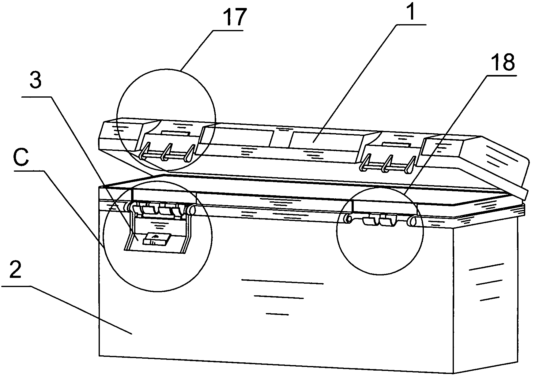
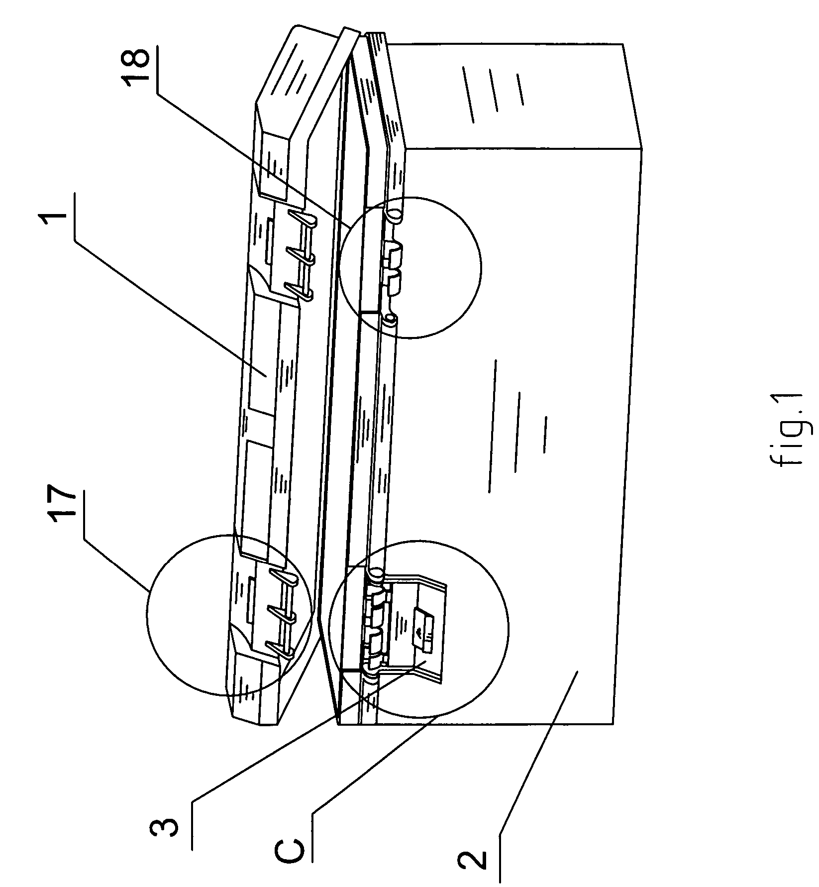
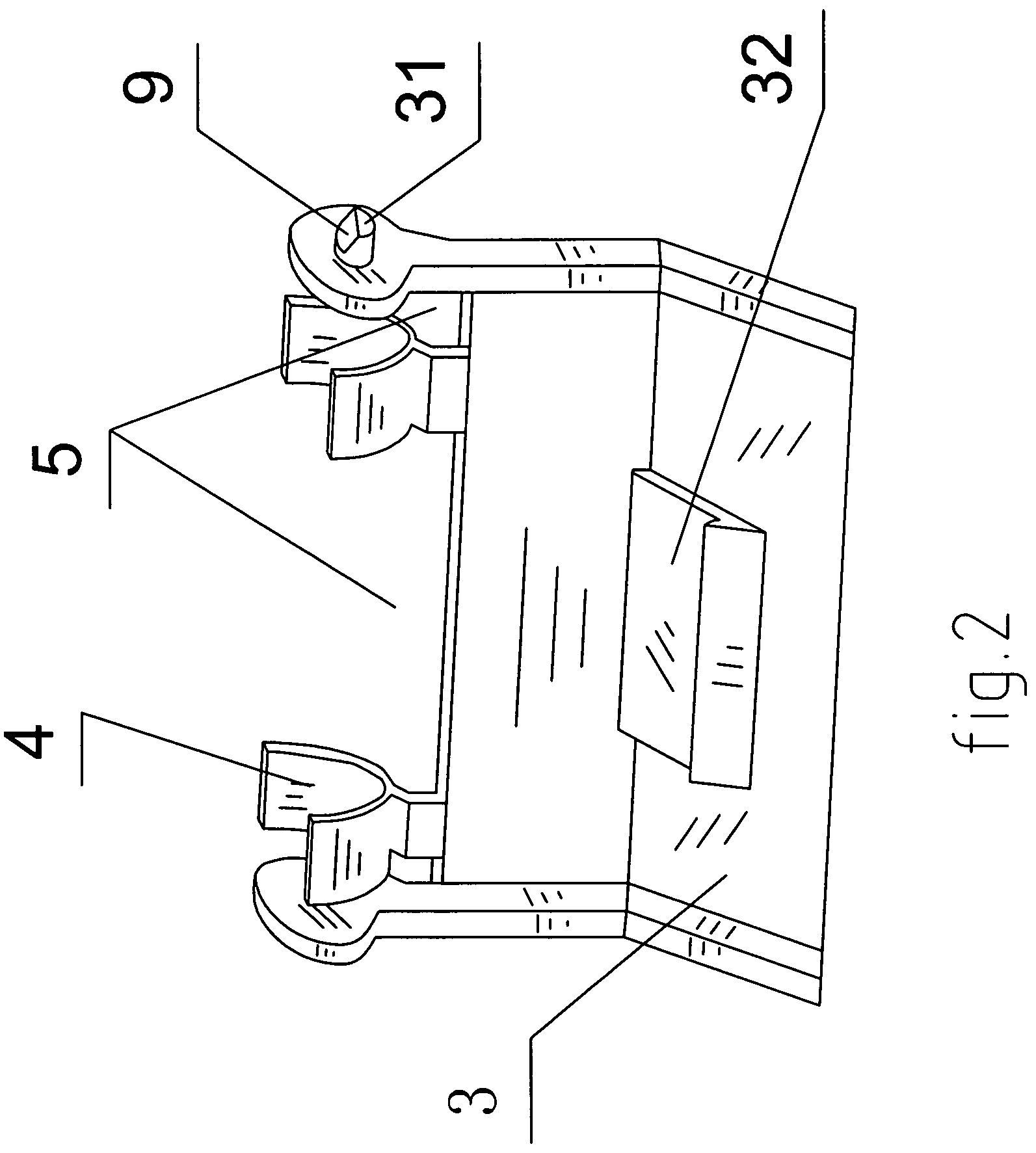
[0018]As shown in FIG. 1 to FIG. 7, according to the utility model the toolbox includes a cover 1, a body 2, and rotary locking device arranged symmetrically on both sides of the toolbox, and the rotary locking device connects the body and the cover, said rotary locking device includes an upper rabbet portion 17 arranged on the cover of the toolbox, a lower rabbet portion 18 arranged on the body of the toolbox, and a clasp plate 3 connecting the upper rabbet portion 17 and the lower rabbet portion 18, the upper rabbet portion 17 includes a locking slot 171 arranged on the cover of the toolbox, a spindle securing bracket 172 and a spindle 173 fitted on the spindle securing bracket 172, on the clasp plate 3 there are rotary locking troughs I 4 corresponding to the spindle 173 and first spaces 5 for inserting troughs I corresponding to the spindle securing bracket 172 and the spindle 172, the clasp plate 3 on it's either sides provided with rotary shafts 31, and on it's middle portion ...


PUM


Abstract

A toolbox includes a cover, a body, and rotary locking devices arranged symmetrically on both sides of the toolbox which connect the body and the cover. Each rotary locking device includes an upper rabbet portion arranged on the cover of the toolbox, a lower rabbet portion arranged on the body of the toolbox, and a clasp plate connecting the upper rabbet portion and the lower rabbet portion. The cover of the toolbox can rotate by the upper rabbet portion rotating around the lower rabbet portion, and they will not disengage due to the locking plate. When opening the toolbox, the locking plate on one side of the tool box is disengaged from the upper rabbet portion, and the cover opens around the rotary locking device arranged on the opposite side of the toolbox. Thus, the toolbox can be opened from either of two sides of the toolbox.

Description

TECHNICAL FIELD[0001]The utility model relates to a toolbox, specifically to a toolbox that can be rotated in two directions to pen the cover of the toolbox.BACKGROUND ART[0002]In the prior art, the toolbox has a cover that can be opened. There are essentially rotary shafts on one side of the toolbox and locking devices on the other side. When the toolbox is to be used, the cover of toolbox is rotated along the rotary shafts, and the toolbox is opened or locked by the locking device on the other side of the toolbox. The toolbox has drawback, that is, the cover can be rotated only in one direction. Moreover, when the toolbox is want to be cleaned more completely, it is difficult and inconvenient to disassemble the cover from the toolbox.SUMMARY OF THE UTILITY MODEL[0003]The objective of the utility model is to provide a toolbox, wherein the cover of the toolbox can be opened by rotating in two directions, and the cover of the toolbox can be disassembled conveniently from the body of ...

Claims


Application Information

Patent Timeline
Patent Type & Authority Patents(United States)
IPC IPC(8): A45C11/26
CPCB25H3/02
Inventor GU, XINJUN
Owner NINGBO HUALEI TOOL
Why Eureka
Try Eureka