Garment hanger rod holder

a technology for hanging rods and garments, which is applied in the direction of rod connections, stands/trestles, fastening means, etc., can solve the problems of minor space error, low precision requirement of metal racks, and inconvenient use, and achieve the effect of convenient us

Inactive Publication Date: 2009-04-14
PROTREND ENTERPRISE CO LTD
View PDF5 Cites 28 Cited by
  • Summary
  • Abstract
  • Description
  • Claims
  • Application Information

AI Technical Summary

Benefits of technology

[0007]A primary object of the present invention is to provide a garment hanger rod holder that could be directly hooked to a front of a metal rack for supporting a garment hanger rod thereon, and is therefore more convenient for use.
[0010]An upper part of the rod holder of the present invention is provided with a vertical slit for engaging with a vertical metal bar at the front of the metal rack, so that the rod holder is prevented from moving laterally relative to the metal rack.

Problems solved by technology

The box 95 of the hanger 94 occupies a large volume and has complicate structure that necessitates relatively high manufacturing cost and causes inconveniences in connecting the hanger 94 to the metal rack 90.
The metal rack for use with the hanger disclosed in U.S. Pat. No. 5,531,416 must have two adjacent metal wires provided at a front end of the top of the metal rack, and is therefore inconvenient for use.
Generally, the metal rack is manufactured with low accuracy requirement, and it tends to have minor error in the space between two adjacent metal wires forming the metal rack.
Therefore, it is possible the hanger could not be easily connected to the metal rack because it has fixed dimensions that might not match the metal rack that has errors in the size thereof.

Method used


Image

  • Garment hanger rod holder
  • Garment hanger rod holder
  • Garment hanger rod holder

Examples


Embodiment Construction

[0024]Please refer to FIG. 5 that shows a garment hanger rod holder 1 according to a preferred embodiment of the present invention configured for assembling to a metal rack 30. The metal rack 30 includes a horizontal top and a vertical front. The front is formed from two spaced horizontal metal bar, namely, an upper and a lower horizontal metal bar 31, 32, and a plurality of spaced short metal bars 33 vertically extended between the upper and lower horizontal metal bars 31, 32 to connect them to each other. The top of the metal rack 30 is formed from a plurality of parallelly spaced metal wires 34 extended in a direction perpendicular to the upper and lower horizontal metal bars 31, 32 at the front of the metal rack 30.

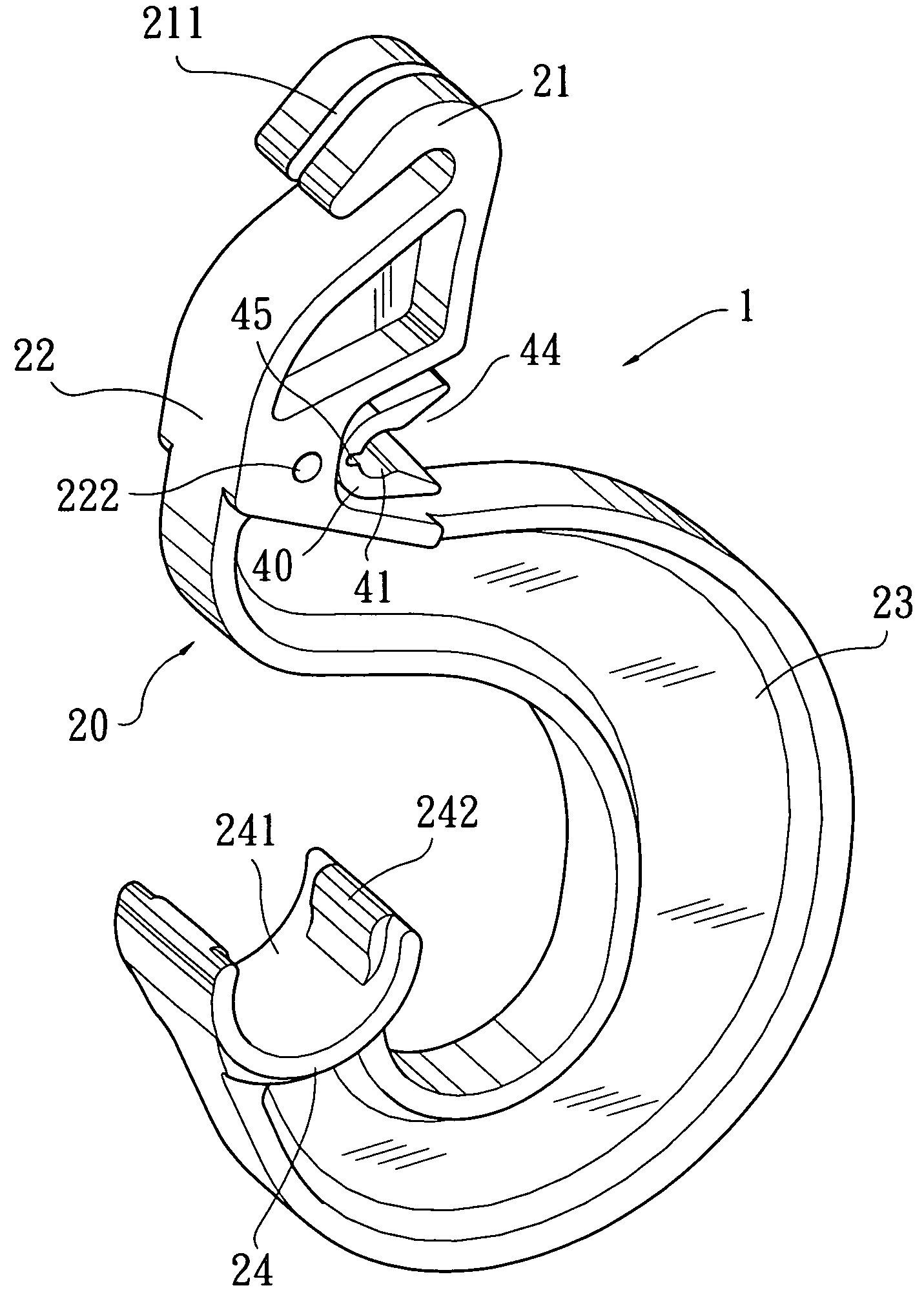
[0025]Please also refer to FIGS. 3 and 4 that are assembled and exploded perspective views, respectively, of the garment hanger rod holder 1, which is also briefly referred to as the rod holder 1 throughout the specification and the appended claims. As shown, the rod ...


PUM


Abstract

A garment hanger rod holder is configured for assembled to upper and lower horizontal metal bars at a front of a metal rack, and includes a main body and a movable member mounted to a rear side of the main body. The main body includes a top hook head for hooking to the upper horizontal metal bar at the front of the metal rack, and a supporting seat formed at a lower free end of the main body for firmly support a garment hanger rod thereon. The movable member defines a receiving space for engaging with the lower horizontal metal bar at the front of the metal rack. The movable member is upward and downward movable relative to the main body to thereby adjust the receiving space to different heights to overcome dimensions errors in the metal rack, and enables the rod holder to firmly assemble to the metal rack.

Description

FIELD OF THE INVENTION[0001]The present invention relates to a garment hanger rod holder, which is directly hooked to a metal rack by engaging with an upper and a lower horizontal metal bars at a front of the metal rack.BACKGROUND OF THE INVENTION[0002]A metal rack is frequently fixed to a wall surface for holding things, so that valuable space in a room could be fully utilized without the need of spending a lot of money for a custom-made cabinet or closet. The metal rack may be covered with curtains or drapes to define a closed storage space and serves as, for example, a cabinet, a closet, or a wardrobe. When the metal rack is used as a wardrobe, it is desirable a garment hanger rod may be fixed below the metal rack for holding some garment hangers.[0003]FIG. 1 shows a conventional metal rack 90 that includes a vertically downward bent front to increase the structural strength of the metal rack 90, preventing the metal rack 90 from easy deformation. An upper and a lower horizontal ...

Claims


Application Information

Patent Timeline
Patent Type & Authority Patents(United States)
IPC IPC(8): F16B45/00
CPCF16B7/0433F16B45/00
Inventor CHEN, HENRY
Owner PROTREND ENTERPRISE CO LTD
Why Eureka
Try Eureka