Pipe insulating coupling with integrated mounting clamp and closure mechanism

a technology of pipe insulation and clamping mechanism, which is applied in the field of pipe insulation coupling, can solve the problems of high cost, inconvenient installation, and laborious clamping, and the means of interconnection are susceptible to wear and tear, and the clamping is labor-intensive, costly and inefficient,

Active Publication Date: 2009-04-21
ZSI
View PDF20 Cites 30 Cited by
  • Summary
  • Abstract
  • Description
  • Claims
  • Application Information

AI Technical Summary

Problems solved by technology

These means for interconnection are, however, susceptible to wear and tear over time.
Many prior art clevis hangers, support devices, and pipe mounting clamps disadvantageously comprise a number of components which must be manipulated and assembled in place.
This is made particularly difficult by the fact that often times this must be done while an installer is standing on a ladder holding the insulated pipe to be supported.
In addition, these types of clevis hangers, support devices, and clamps are labor intensive, costly and inefficient.

Method used


Image

  • Pipe insulating coupling with integrated mounting clamp and closure mechanism
  • Pipe insulating coupling with integrated mounting clamp and closure mechanism
  • Pipe insulating coupling with integrated mounting clamp and closure mechanism

Examples


Embodiment Construction

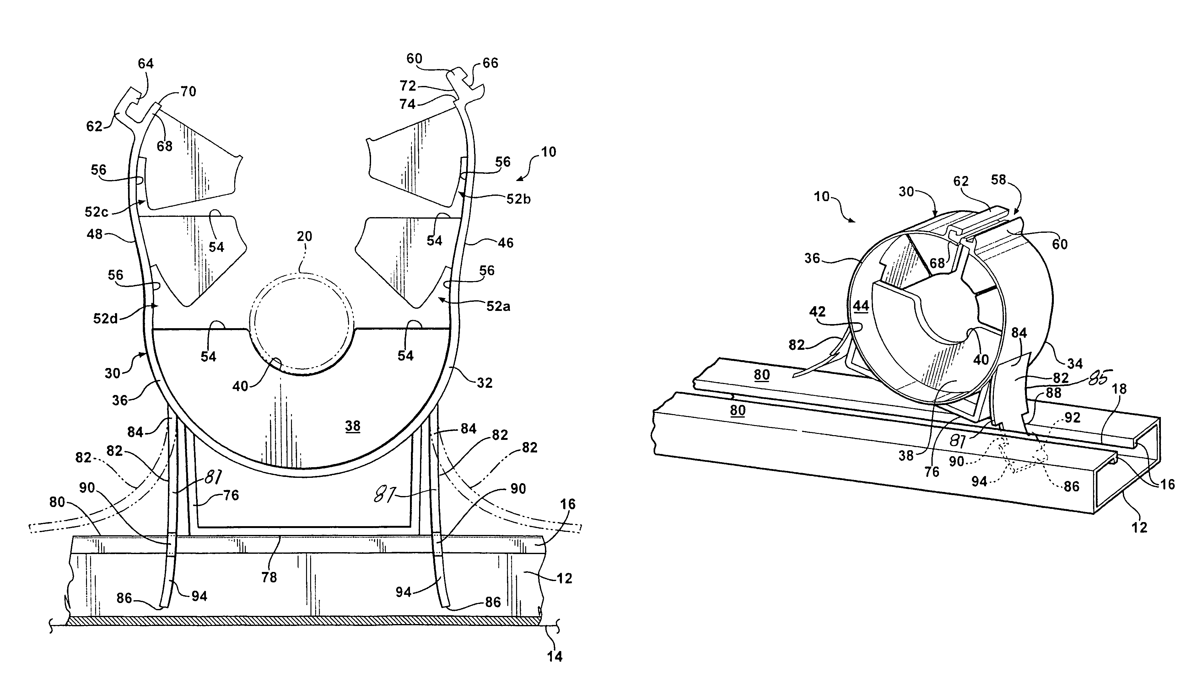
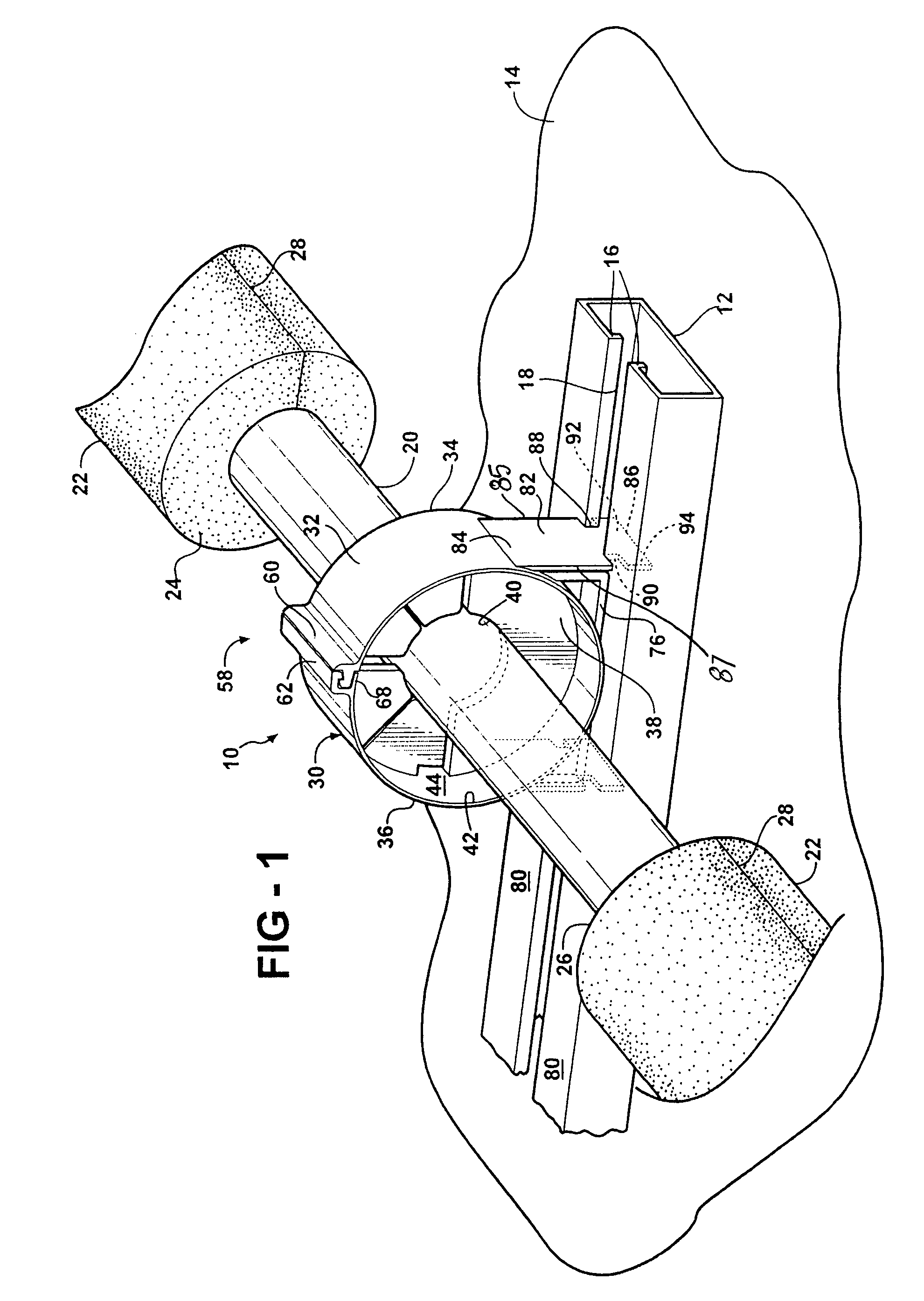
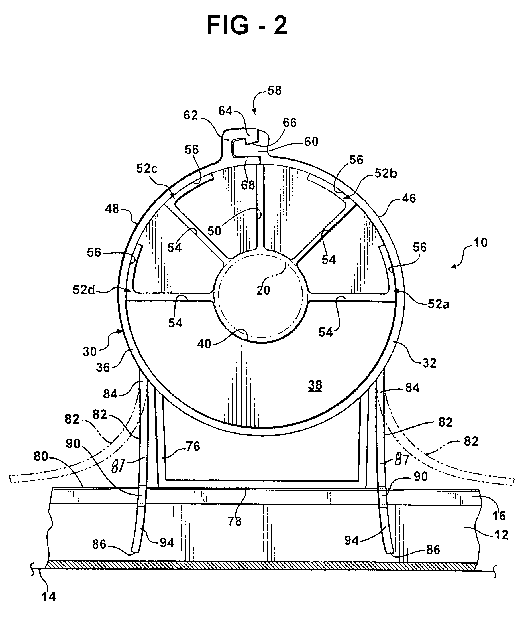
[0021]Referring to FIG. 1, a pipe insulation coupling, generally shown at 10, is mounted to a length of channel-section track 12 which is secured to a generally planar supporting structure 14, such as a floor, ceiling, wall or similar surface. The channel-section track 12 is commonly known in the art and has a pair of inwardly turned edges or flanges 16 defining a slot 18 therebetween extending longitudinally between opposing ends. The pipe insulation coupling 10 supports an elongated tubular pipe 20 for transferring fluids or gases therethrough and retains an elongated insulation tubing 22 encased around the pipe 20. More specifically, the pipe insulation coupling 10 retains adjacent ends 24, 26 of two separate portions of the insulation tubing 22 adjacent one another to ensure that an entire length of the pipe 20 remains insulated even as the pipe 20 is exposed to wear and tear. The insulation tubing 22, which is commonly formed from cellular polyurethane foam, is provided in pred...


PUM


Abstract

A pipe insulation coupling secures a pipe and adjacent ends of insulation tubing surrounding the pipe to a channel-section track having a pair of inwardly turned flanges. The coupling includes a one-piece elongated cylindrical body having an outer tube wall extending between first and second ends. A planar interior wall disposed midway between the first and second ends extends inwardly from the outer tube wall to a center bore for receiving the pipe therethrough. The planar wall defines opposing first and second channels extending from the planar wall to the first and second ends for receiving the adjacent ends of the insulation tubing therein. A pair of flexible and resilient legs extends between a proximal end fixedly secured to the outer tube wall and a distal end including opposing notches formed therein for selective engagement with the flanges of the track thereby locking the coupling to the track.

Description

BACKGROUND OF THE INVENTION[0001]1. Field of the Invention[0002]The invention relates to a pipe insulation coupling for supporting a pipe along a support structure. More particularly, the invention relates to a pipe insulation coupling having an integrated mounting clamp to support a pipe, which is encased by insulation tubing, along a support structure and an integrated closure mechanism.[0003]2. Description of Related Art[0004]Conventional pipes are used to convey or transfer fluids or gases in various industrial applications, such as sprinkler systems, refrigeration systems, and heating and cooling systems. These pipes are commonly encased in a cellular foam pipe insulation tubing, which maintains the fluids within the pipes at a desired temperature. The pipe insulation tubing is typically provided in predetermined lengths that are aligned end-to-end to cover an entire length of the pipe. It is desirable to interconnect adjacent ends of the pipe insulation tubing along the pipe t...

Claims


Application Information

Patent Timeline
Patent Type & Authority Patents(United States)
IPC IPC(8): F16B45/00
CPCF16L3/1211F16L3/24F16L59/135F16L3/243F16L3/2431
Inventor OPPERTHAUSER, ORVAL A
Owner ZSI
Why Eureka
Try Eureka