High comfort sound delivery system

a high comfort and sound technology, applied in the direction of transducer details, ear supports, instruments, etc., can solve the problems of the relatively complex mechanism of the apparatus that still does not provide for a full three-dimensional adjustment, and does not provide any means for the adjustment of the distal portion

Inactive Publication Date: 2009-04-21
DOLBY LAB LICENSING CORP
View PDF8 Cites 27 Cited by
  • Summary
  • Abstract
  • Description
  • Claims
  • Application Information

AI Technical Summary

Benefits of technology

[0016]Accordingly, it is an object of the present invention to provide a communications earpiece which will be comfortable to wear, even for extended periods of time.

Problems solved by technology

Many people find this to be a solution which is useful for short periods of time, but which may be uncomfortable, especially when used for extended periods of time.
Otherwise, the high gain of the hearing aid amplifier would cause feedback of the sound “leaking” out of the user's ear.
However, the relatively complex mechanism of that apparatus still does not provide for a full three dimensional adjustment.
Also like the '235 patent, the device taught and claimed in the '183 patent does not provide any means for the adjustment of the distal portion thereof fully in all axes of rotation.
The earmold is nearly totally occluding, so the sound is unnatural, and for comfort the earmold must be custom shaped for the individual user's ear which is generally not a desirable feature for a consumer product.
High occlusion is achieved through custom earmolds or nearly occluding foam tips on the ends of the tubes, but such high occlusion makes the sound of the user's own voice very unnatural and disturbing to the user.
It is believed that prior art devices, while being useful for their intended purposes, have not provided a solution wherein user comfort, sound quality, feedback prevention, and other desirable qualities are found without significant sacrifice of at least one of these qualities in favor of another.

Method used


Image

  • High comfort sound delivery system
  • High comfort sound delivery system
  • High comfort sound delivery system

Examples


Embodiment Construction

[0046]The embodiments and variations of the invention described herein, and / or shown in the drawings, are presented by way of example only and are not limiting as to the scope of the invention. Unless otherwise specifically stated, individual aspects and components of the invention may be omitted or modified, or may have substituted therefore known equivalents, or as yet unknown substitutes such as may be developed in the future or such as may be found to be acceptable substitutes in the future. The invention may also be modified for a variety of applications while remaining within the spirit and scope of the claimed invention, since the range of potential applications is great, and since it is intended that the present invention be adaptable to many such variations.

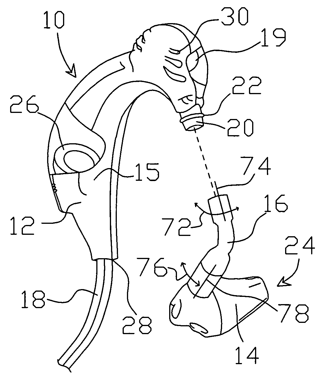
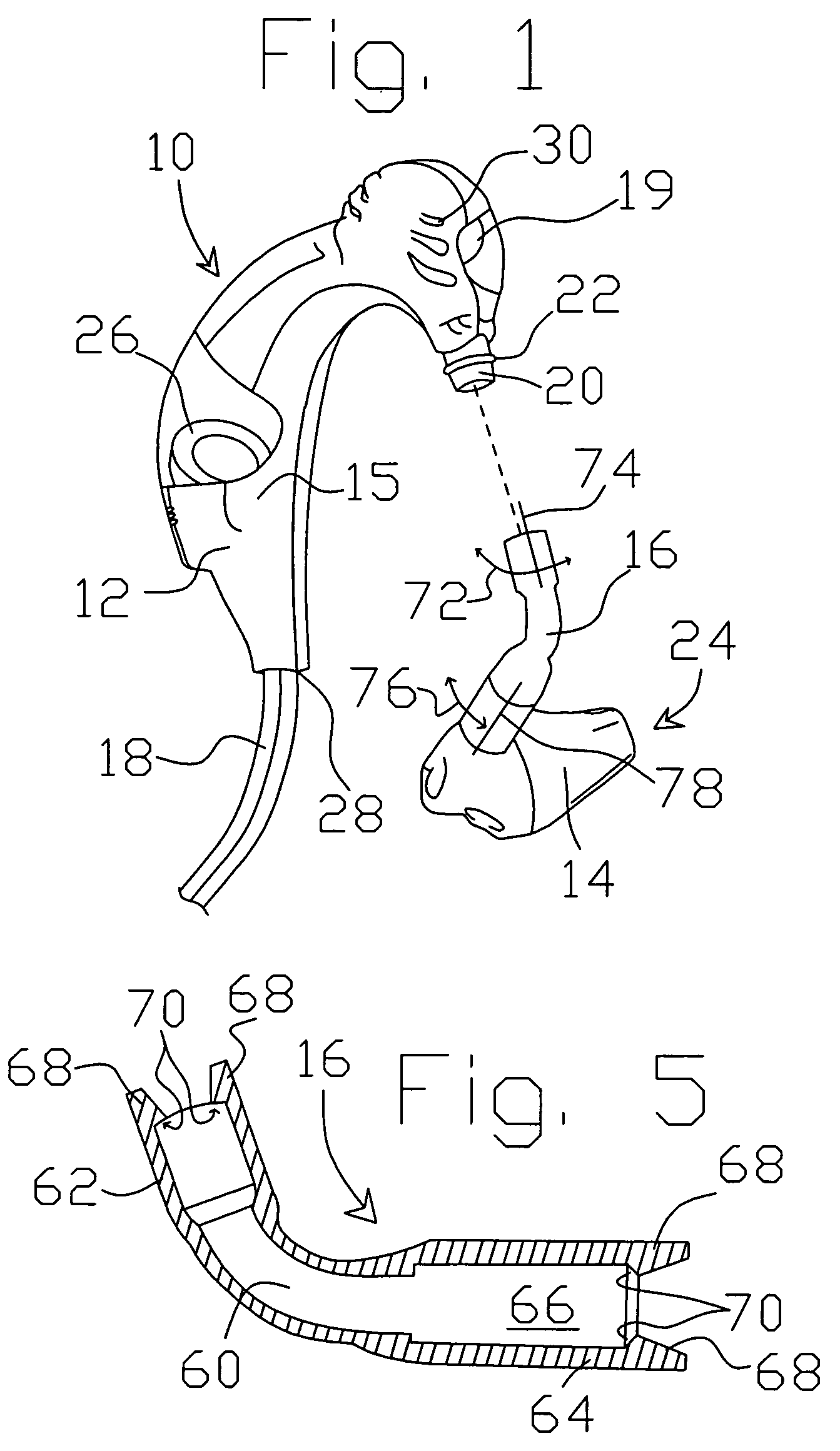
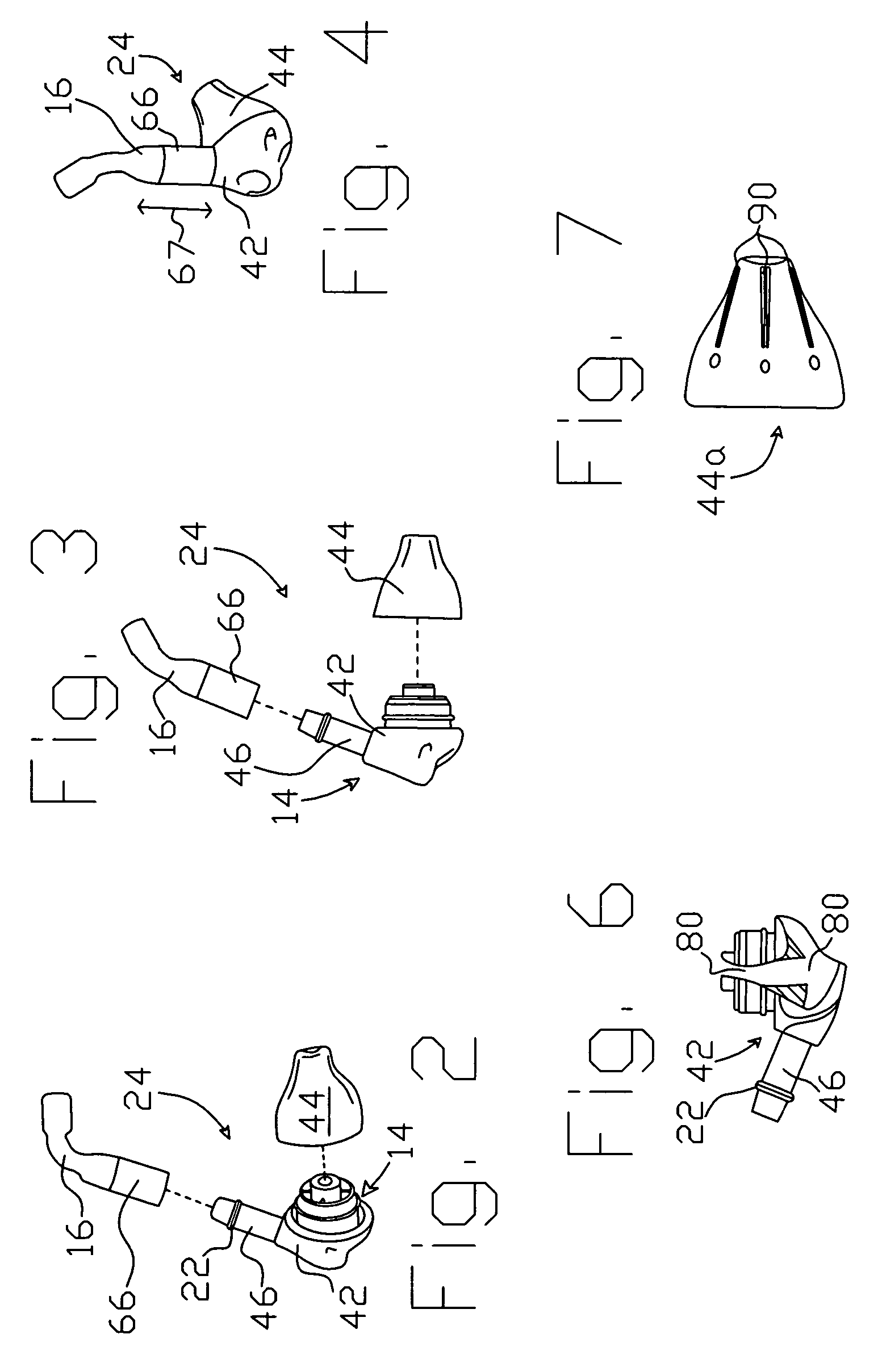
[0047]An example of a mode for carrying out the invention is a high comfort sound delivery system. The inventive high comfort sound delivery system is depicted in a partially cut away, partially exploded, perspective vie...


PUM


Abstract

A high comfort sound delivery system (10) for use with a personal communications device such as a telephone. The high comfort sound delivery system (10) has a behind-the-ear member (12) for holding the device on or near an ear of the user, and a sound horn (14) to be positioned at or near the ear canal of the user. Sound is produced by a speaker (26) in a speaker enclosure portion (15) of the behind-the-ear piece (12) and is delivered to the sound horn (14) through a generally flexible connecting member (16). Rotational adjustment is provide to rotating the connecting member (16) in relation to a speaker tube connection projection (20) and / or a sound horn tube connection projection (46). A length adjustment is provided by moving an elongated portion (66) of the connecting member (16) of the sound horn tube connection projection (46). Alternate sound horn bodies (42a, 42b, 42c, 42d, 42e, 42f) provide addition rotational adjustment points.

Description

RELATED APPLICATIONS[0001]This application is a continuation-in-part of U.S. patent application Ser. No. 10 / 336,235 filed on Jan. 3, 2003 now abandoned by the same inventors, which is a continuation of U.S. patent application Ser. No. 10 / 041,771 filed on Jan. 7, 2002 now abandoned. These applications are incorporated herein by reference in their entirety.TECHNICAL FIELD[0002]The present invention relates to the field of audio transducer earpiece devices, and more particularly to an earpiece for use with electronic communications devices. The predominant current usage of the present inventive high comfort sound delivery system is in conjunction with portable personal communications devices, such as cellular or cordless telephones, two way radios, and the like, wherein it is desirable to have an apparatus for delivering sound to the ear of the user in a manner which does not cause discomfort to the user even when used over extended periods of time.BACKGROUND ART[0003]Personal two way ...

Claims


Application Information

Patent Timeline
Patent Type & Authority Patents(United States)
IPC IPC(8): H04R1/10
CPCH04R1/1058H04R1/1016H04R1/1066H04R1/345
Inventor DOBRAS, DAVID Q.TAENZER, JON C.
Owner DOLBY LAB LICENSING CORP
Why Eureka
Try Eureka