
Method and apparatus for providing automatic frame relay and ATM provisioning of network devices

Active Publication Date: 2009-04-21
CISCO TECH INC
View PDF49 Cites 44 Cited by
  • Summary
  • Abstract
  • Description
  • Claims
  • Application Information

AI Technical Summary

Benefits of technology

[0069]According to one embodiment, automatically provisioning devices operable with internet protocol (IP) in a virtual circuit network is facilitated by configuration commands that can instruct the device to connect to a configuration server using a frame relay or ATM network without specifying connection information, such as an identity of the virtual circuit or IP address to use for the connection.
[0070]In one embodiment compatible with the Cisco CLI command syntax, new commands, “cns connect” and “cns template connect” are introduced so that individual instances of active virtual circuits

Problems solved by technology

In network environments in which frame relay and ATM technologies are present, however, the technique of using a generic bootstrap configuration is presented with new issues.
Using a fixed preset DLCI in any generic bootstrap configuration, for example, would fail in instances where such devices must establish connectivity across multiple regions or service providers using disparate DLCI numbering conventions.
In such situations, the DLCI number presented to CPE devices in the customer premises is heterogeneous throughout the network and there cannot be any assumption made about its value with respect to what is encoded in the bootstrap configuration.
Accordingly, in such applications, merely shipping a CPE with a generic configuration having therein, a preset DLCI would not address the problem sufficiently in all cases.
Therefore, to date, there has been no way to automate the configuration of network devices with templates.

Method used


Image

  • Method and apparatus for providing automatic frame relay and ATM provisioning of network devices
  • Method and apparatus for providing automatic frame relay and ATM provisioning of network devices
  • Method and apparatus for providing automatic frame relay and ATM provisioning of network devices

Examples


Embodiment Construction

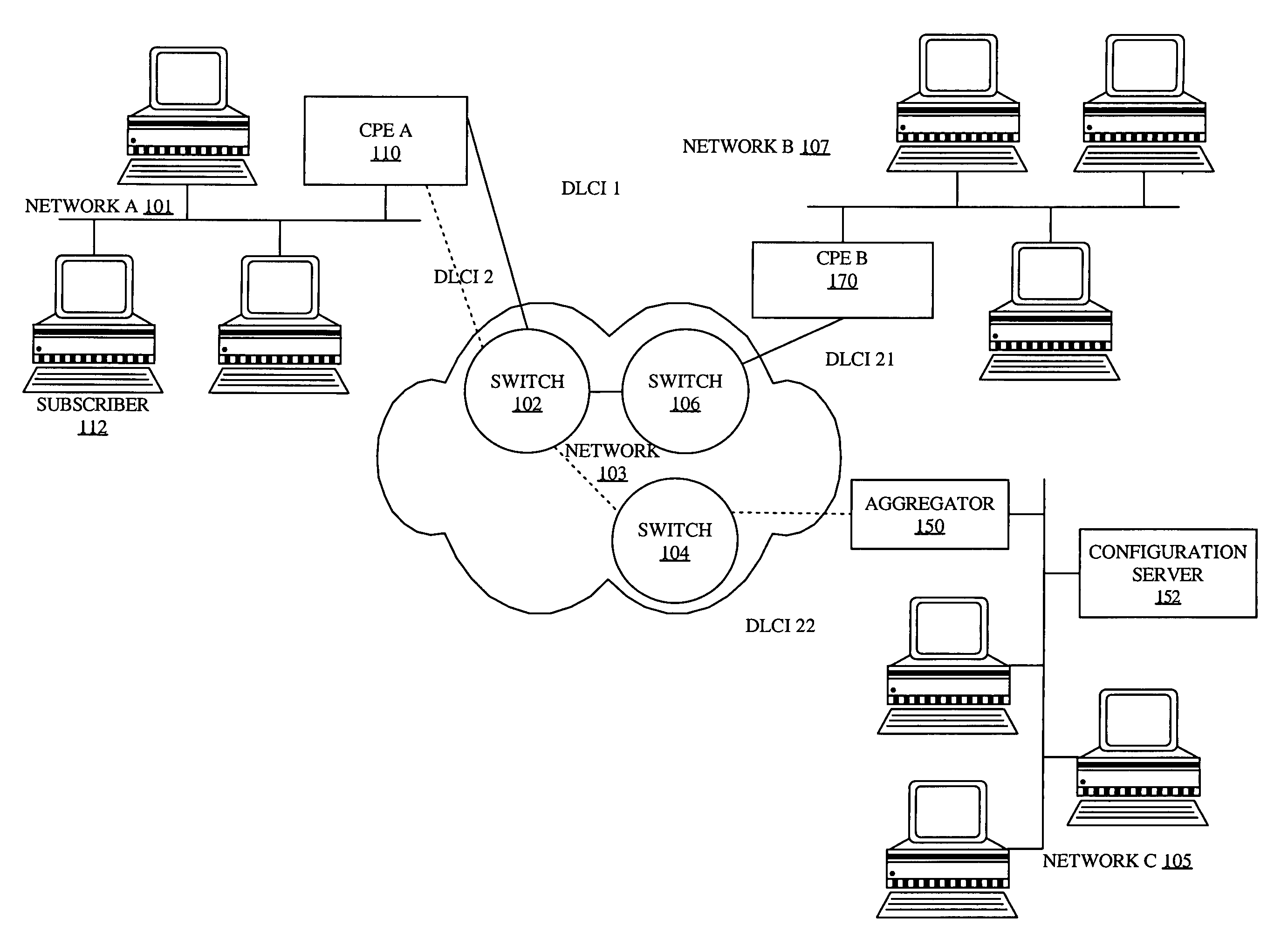
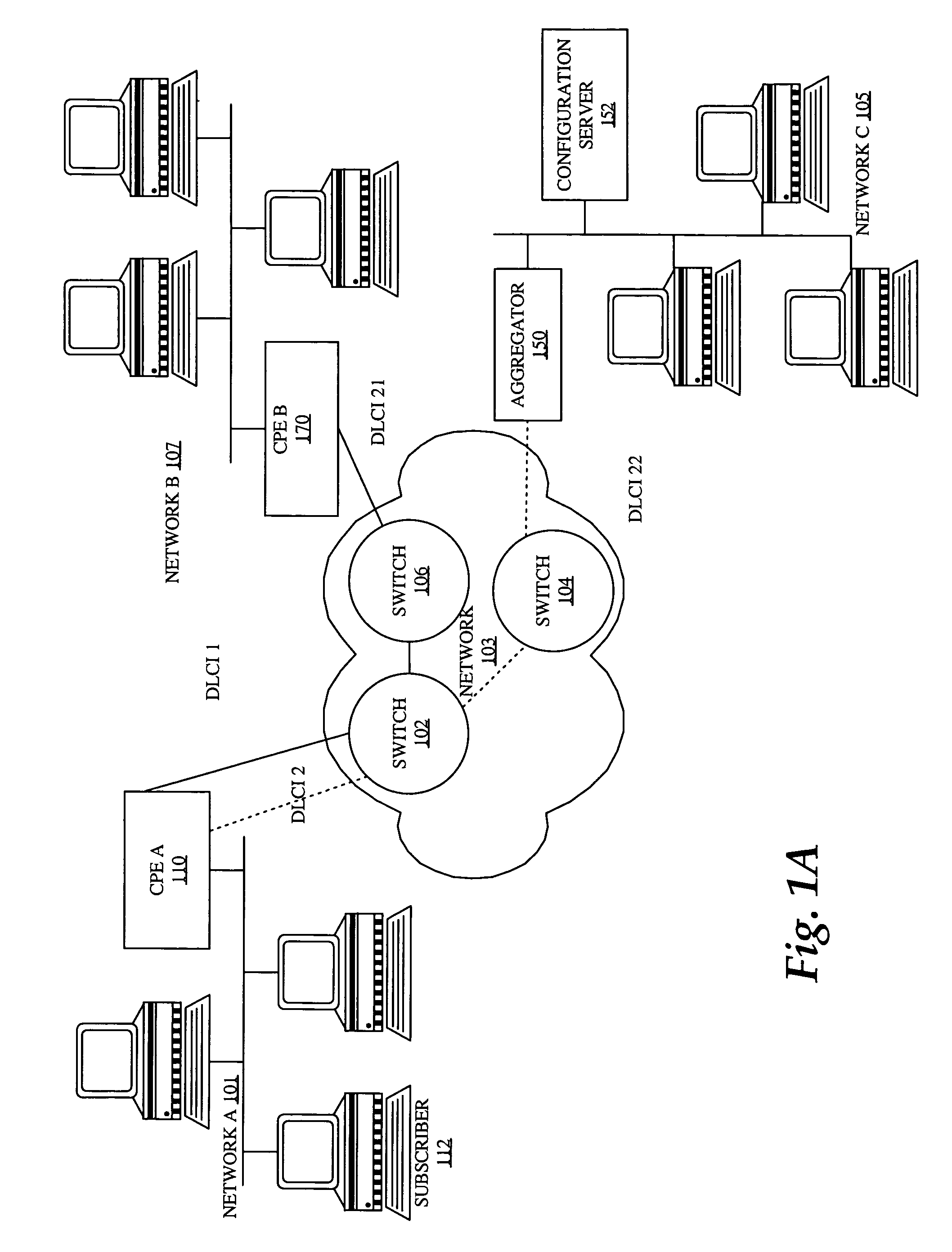
[0021]A method and apparatus for automating frame relay and ATM provisioning of network devices is described. In the following description, for the purposes of explanation, numerous specific details are set forth in order to provide a thorough understanding of the present invention. It will be apparent, however, to one skilled in the art that the present invention may be practiced without these specific details. In other instances, well-known structures and devices are shown in block diagram form in order to avoid unnecessarily obscuring the present invention.

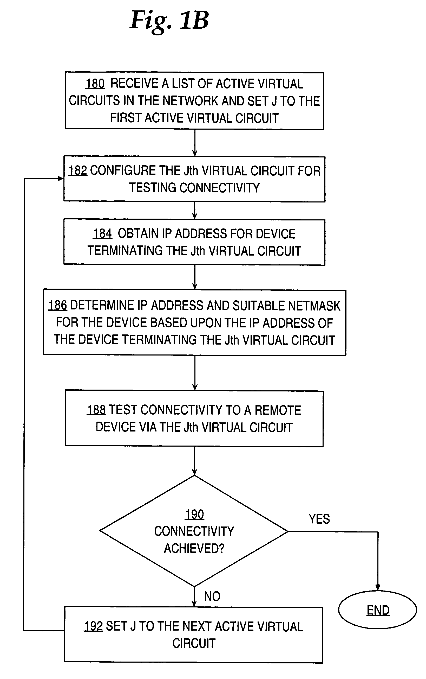
[0022]Embodiments are described herein according to the following outline:[0023]1.0 General Overview[0024]2.0 Structural and Functional Overview[0025]3.0 Method of Automating Frame Relay and ATM Provisioning of a Network Device[0026]3.1 Overview[0027]3.2 Obtaining and Processing a List of Active DLCIs[0028]3.3 Obtaining an IP Address for the Device Terminating the Virtual Circuit[0029]3.4 Determining an IP Address and a Suitabl...


PUM


Abstract

A method is disclosed for automatically provisioning network devices for use with virtual circuit networks, such as frame relay and ATM networks. The device receives a list of identifiers corresponding to virtual circuits from a configuration interface for the virtual circuit network. The device iteratively applies each identifier from the list to individual instances of interface configuration commands and attempts to provide connectivity with a remote device. Once a configuration command is applied, the device will obtain an IP address for a device terminating the virtual circuit corresponding to the identifier selected from the list; and determines an IP address for itself. The device tests the virtual circuit for connectivity with the remote device. If the device is able to determine that the virtual circuit corresponding to the selected identifier provides connectivity to the remote device, then that virtual circuit is used to connect to the remote device.

Description

CROSS-REFERENCE TO RELATED APPLICATIONS[0001]This application is related to the following commonly-owned, co-pending U.S. patent applications, the entire contents of which is hereby incorporated by reference as if fully set forth herein:[0002](a) U.S. patent application Ser. No. 10 / 422,227, entitled, “Method And Apparatus Providing Automatic Connection Announcement From A Modular Network Device To A Network Management Point,” by Arnold Stamler and Ikramullah Mohammed, filed Apr. 23, 2003;[0003](b) U.S. patent application Ser. No. 10 / 422,231, entitled, “Method And Apparatus For Automatically Synchronizing A Unique Identifier Of A Network Device”, by Arnold Stamler, filed Apr. 23, 2003; and[0004](c) U.S. patent application Ser. No. 10 / 434,586, entitled, “Method And Apparatus Providing Automatic Provisioning Of Modular Network Devices”, by Arnold Stamler and Ikramullah Mohammed, filed May 8, 2003.FIELD OF THE INVENTION[0005]The present invention generally relates to deploying network d...

Claims


Application Information

Patent Timeline
IPC IPC(8): G06F15/173
CPCG06F15/173
Inventor NG, JOHNFOWLER, GREGORY A.STAMLER, ARNOLD L.RICHARDS, ANTONYPAKKAM, SAIRAJ
Owner CISCO TECH INC
Features
  • Generate Ideas
  • Intellectual Property
  • Life Sciences
  • Materials
  • Tech Scout
  • Unparalleled Data Quality
  • Higher Quality Content
  • 60% Fewer Hallucinations
Learn More