Filling valve apparatus for a beverage filling machine

a filling valve and beverage technology, applied in liquid handling, packaging goods types, transportation and packaging, etc., can solve the problems of corroding certain parts of the filling valve apparatus may begin to wear, so as to reduce downtime and quick and easy removal

Inactive Publication Date: 2009-04-28
ADCOR INDS
View PDF34 Cites 9 Cited by
  • Summary
  • Abstract
  • Description
  • Claims
  • Application Information

AI Technical Summary

Benefits of technology

[0009]Accordingly, the release mechanism being selectively coupled to the primary valve portion and moveable between the engaged position and the disengaged position allows the replacement valve portion to be quickly and easily removed from the filling valve apparatus and replaced. This helps to reduce downtime when operating the beverage filling machine. In addition, the release mechanism may be placed in various locations on the filling valve apparatus, allowing multiple parts of the filling valve apparatus to act as the primary valve portion and the replacement valve portion. Furthermore, the release mechanism of the subject invention allows the parts of the filling valve apparatus to be more easily removed.

Problems solved by technology

However, as the filling valve apparatus is used, certain parts of the filling valve apparatus may begin to wear.
For instance, the liquid being injected into the beverage container with the filling valve apparatus may corrode certain parts of the filling valve apparatus.
Replacing the corroded parts of the filling valve apparatus can be difficult and time consuming since this often requires removing and replacing the entire filling valve apparatus, which takes considerable time.
When filling large quantities of bottles each day, stopping the beverage filling machine to replace the filling valve apparatus reduces production and results in lost profits.

Method used


Image

  • Filling valve apparatus for a beverage filling machine
  • Filling valve apparatus for a beverage filling machine
  • Filling valve apparatus for a beverage filling machine

Examples


first embodiment

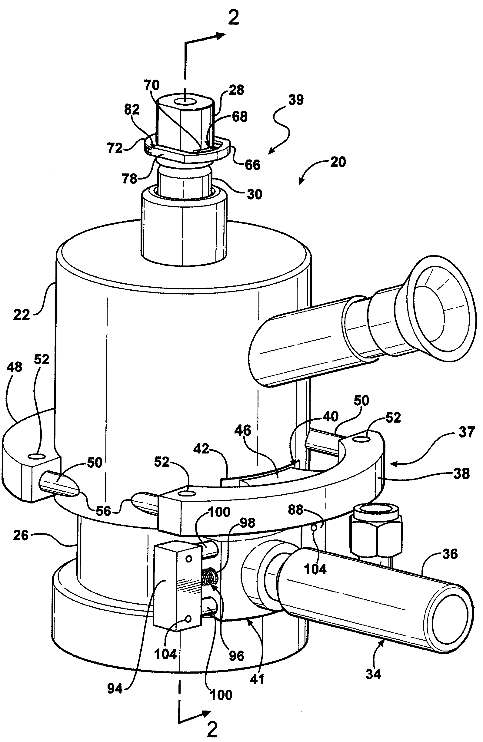
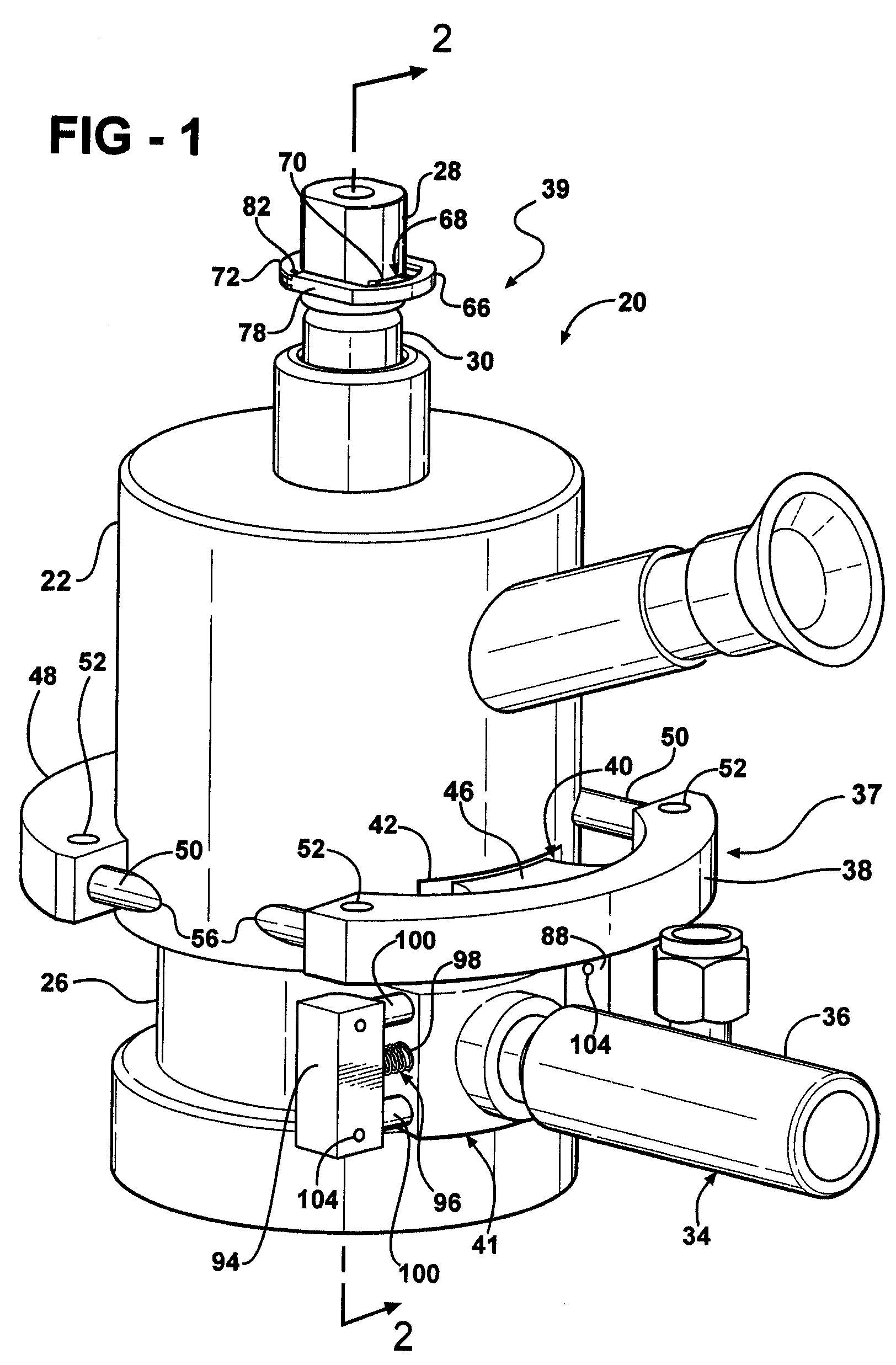
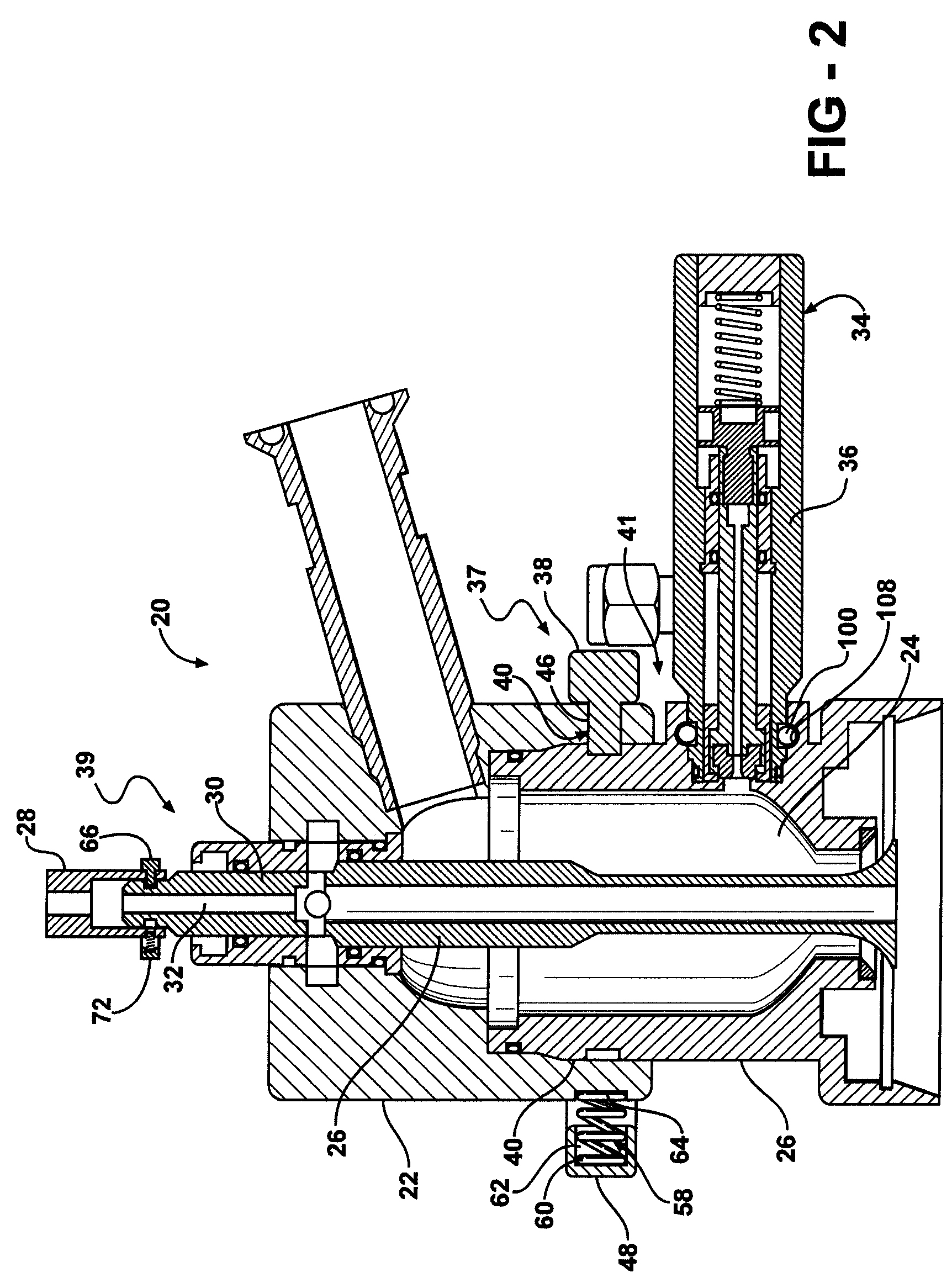
[0027]Referring now to FIGS. 1-5, in a first embodiment, the filling valve apparatus 20 includes the valve body release mechanism 37 supported by the upper portion 22 and slideably disposed between the engaged position for securing the lower bell 26 to the upper portion 22 and a disengaged position for releasing the lower bell 26 from the upper portion 22. In this embodiment, the upper portion 22 is the primary valve portion and the lower bell 26 is the replacement valve portion. The valve body release mechanism 37 includes a locking handle 38 having a locking element 40 for securing the upper portion to the lower bell when in the engaged position. Generally, the primary valve portion defines an aperture 42 and the replacement valve portion defines a corresponding groove 44 for receiving the locking element 40 in the aperture 42 and the groove 44 and supporting the release mechanism on the primary valve portion. Therefore, in this embodiment, the upper portion defines the aperture 4...

second embodiment

[0032]Referring now to FIGS. 1, 2, and 6-8, in a second embodiment, the valve stem release mechanism 39 is supported by the adapter 28 and slideably disposed between a locked position for securing the stem 30 to the adapter 28 and an unlocked position for releasing the stem 30 from the adapter 28. In this embodiment, the adapter 28 is the primary valve portion and the stem 30 is the replacement valve portion. The valve body release mechanism 37 includes a locking handle 66 having a locking element 68, such as a tooth 70 as previously described, and a release handle 72 having a biasing element 74, such as a spring 76 as previously described. In addition, the adapter 28 defines a pocket 77 and the biasing element 74 extends from a cavity 79 defined by the release handle 72 into the pocket 77 for biasing the valve stem release mechanism 39 in the engaged position. Here, the biasing element 74 is disposed in the cavity 79 between the release handle 72 and the adapter 28.

[0033]The valve ...


PUM

PropertyMeasurementUnit
timeaaaaaaaaaa
pressureaaaaaaaaaa
forceaaaaaaaaaa

Abstract

A filling valve apparatus for a beverage filling machine includes a primary valve portion. A replacement valve portion is coupled to the primary valve portion. A release mechanism is slideably mounted to the primary valve portion. The release mechanism selectively couples the replacement valve portion to the primary valve portion, and the release mechanism is moveable between an engaged position securing the replacement valve portion to the primary valve portion and a disengaged position releasing the replacement valve portion from the primary valve portion.

Description

CROSS REFERENCE TO RELATED APPLICATION[0001]This application claims the benefit of provisional patent application Ser. No. 60 / 723,536 filed Oct. 4, 2005.BACKGROUND OF THE INVENTION[0002]1. Field of the Invention[0003]The present invention generally relates to a filling valve apparatus for a beverage filling machine.[0004]2. Description of the Related Art[0005]Filling valve apparatuses for beverage filling machines are known in the art for injecting liquids into beverage containers. However, as the filling valve apparatus is used, certain parts of the filling valve apparatus may begin to wear. For instance, the liquid being injected into the beverage container with the filling valve apparatus may corrode certain parts of the filling valve apparatus. Once corroded, those parts of the filling valve apparatus must be replaced before the beverage filling machine may continue operating. Replacing the corroded parts of the filling valve apparatus can be difficult and time consuming since t...

Claims


Application Information

Patent Timeline
Patent Type & Authority Patents(United States)
IPC IPC(8): B65B3/04
CPCB65B39/004B65B59/04B67C3/001B67C3/26
Inventor STAVRAKIS, DEMETRIOSBROWN, MICHAEL J.RUBLE, EDWIN K.
Owner ADCOR INDS
Why Eureka
Try Eureka