Centripetal reflex method of space launch

a space launch and centripetal reflex technology, applied in the field of space launch methods, can solve the problems of increasing the weight necessary to be endured by all lower sections, the potential need for such a seaplane transport in the tsunami tragedy of late 2004/early 2005 in se asia became glaringly obvious, and the effect of enhancing the payload and reducing the cost of payroll

Inactive Publication Date: 2009-04-28
COOK MICHAEL LEON
View PDF14 Cites 24 Cited by
  • Summary
  • Abstract
  • Description
  • Claims
  • Application Information

AI Technical Summary

Problems solved by technology

This penalty becomes especially acute because the tremendous acceleration rate of conventional V-2 type rockets greatly increases the weight necessary to be endured by all lower sections.
(a) to provide an economical means of lifting reasonable amounts of mass into a variety of sub-orbits, orbits, or to assist the objects in attaining escape velocity. It must be understood that the term “economical” presumes that the tools enlisted to express the centripetal reflex method of space launch (a method, after all) will be flexible enough to serve mankind's needs in other fashions. The expensive and irreversibly expendable first stage of a conventional rocket like the Saturn V obviously does not pass such a test. The present invention promises much greater mission flexibility at lowered cost as well. The Hubble space telescope may be destroyed by 2007 due to the lack of a billion dollars for the manned space mission to fix and supply Hubble. By means of the centripetal reflex method of space launch a 5,000 kg rocketplane or several of them could reach Hubble altitude on a few days notice for much less expense.
(b) as mentioned previously, one of the problems with any space launch system that attains high Mach numbers while still in the atmosphere is what happened to the shuttle Columbia.
A fortuitous aspect of the centripetal reflex design is that anything that shakes loose from any part of the lengthy system will tend to be carried by the slipstream away from other assemblies.
The potential need for such a seaplane transport in the late 2004 / early 2005 tsunami tragedy in SE Asia became glaringly obvious.
Conventional airplanes could not take desperately needed relief supplies directly to the locations of greatest need.
Crowded conventional airports and devastated ground infrastructure such as roads and bridges cost thousands of lives.
When launching unmanned space vehicles the performance of this method may be significantly increased, for one calculable limitation upon the concept is the necessity of not exceeding accelerations that humans can endure.
It is not inconceivable that some lighter loads could be propelled to escape velocity without rocket assistance by the reflex method, even also without the optimal existing aircraft posited earlier.
We will presently claim several peripheral innovations that may be costly to develop, but they are not essential to the good operation of the centripetal reflex method of space launch.
The cost of developing the very large American tow aircraft of the additional embodiment might be a problem, but it was argued long and hard in (c), (d), and (e) how such an airplane could justify its development through other uses that would be important to humanity.
The challenge is to create one or several types of multi-purpose aircraft, preferably of very large size, in an age when most new conceptions are intended as extremely special purpose tools to fit narrow market niches.

Method used


Image

  • Centripetal reflex method of space launch
  • Centripetal reflex method of space launch
  • Centripetal reflex method of space launch

Examples


embodiment — figs 1a to 11

—PREFERRED EMBODIMENT—FIGS 1A TO 11

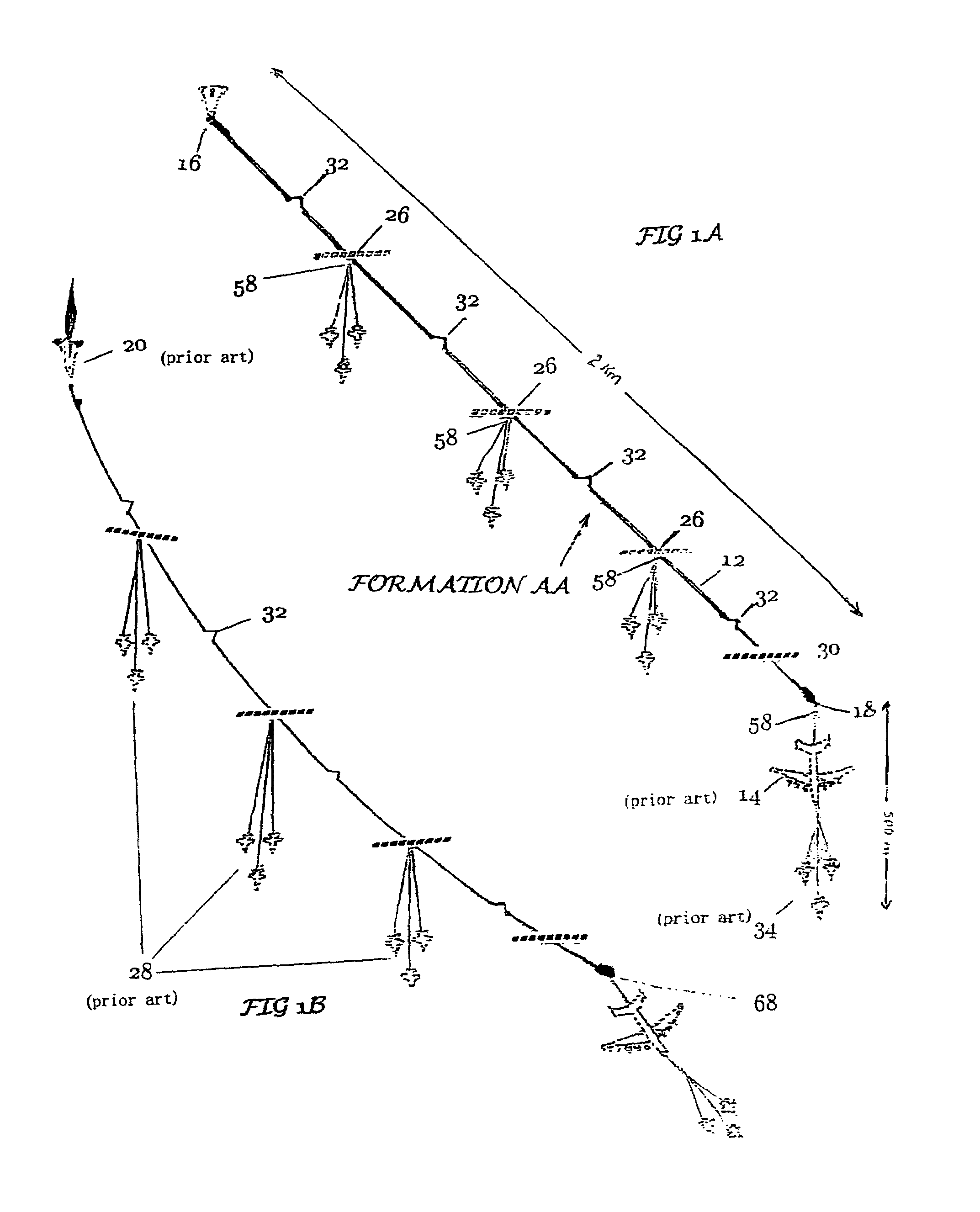
[0206]FIG. 1A is a top plan view of flight-worthy Formation AA constructed in accordance with the centripetal reflex method of space launch and pictured on a sufficiently wide runway at time T=−10 in takeoff ready mode prior to takeoff roll. Even after takeoff and during the ascension mode the elements of Formation AA will maintain this general relationship to each other, reference logic steps 100-104 in FIG. 2B. Tow pipeline 14 in this embodiment is two kilometers in length and is pictured in abbreviated form to fit the page. Since the angle of presentation that Formation AA makes to the runway is 45 degrees, the runway (not shown) must be at least 1.414 km wide or wider, to accommodate the variables of landing. The length of the runway should be about 4 km.

[0207]Tow pipeline 14 is connected to large transport aircraft 40 by pivot yoke 18. A launch load 20 is attached to fixed end cap 16 by latching mechanism 150. Close by can be seen the first of...


PUM


Abstract

A method of launching space vehicles by towing them aloft, then twirling them around a large transport aircraft (40) at the center of a formation (AA) of other tow aircraft (28, 34) and other devices of the invention. A lengthy, semi-rigid tow pipeline (14) serves as a conduit for the transfer of fuels and oxidizers, as the tow cable, and as an energy storage device that reflexes efficiently when it is flexed. The flexing of tow pipeline (14) is caused by a parachute (22) acting in conjunction with all the aircraft making the tighest turn they are capable of doing. Tow aircraft in certain arrays (28) are joined to tow pipeline (14) by sliding trollies (26) that also host canard rotor wings for the aerodynamic support of the main tube (12). The tow trollies (26) aid the sliding tow aircraft arrays (28) in gaining mechanical advantage to accelerate the space vehicle. The space vehicle may also burn its own motors for a longer-than-usual time as it gains in angular velocity because its fuels are replenished by a pipeline that automatically increases the pressure and volume of fuel flow as the angular acceleration increases. The tow pipeline (14) features a micro-hole laminar lift foil (50) on the top surface of the wing and on the bottom. By balancing the vacuum level in the plurality of chamber underneath the plurality of lift foil 50, the pilot or autopilot has an effective way to control the flight characteristics of the tow pipeline (14). In some embodiments the micro-hole laminar lift foil (50) on the top and bottom will made of transparent hollow wire segments or other material so arranged as to pass ambient light through to photo-voltaic cells below that convert sunlight to electrical energy.

Description

CROSS-REFERENCE TO RELATED APPLICATIONS[0001]Not ApplicableFEDERALLY SPONSORED RESEARCH[0002]NoneSEQUENCE LISTING[0003]NoneBACKGROUND OF THE INVENTION[0004]1. Field of Invention[0005]This invention relates to a space launch method whereby a large transport aircraft with the assistance of other apparatus and aircraft tows an intended space load close to the stratosphere and performs specific maneuvers to transfer kinetic energy and a plurality of fuels from a plurality of tow vehicles and structures to the towed load, which will thereafter accelerate by an order of magnitude or more due to the effects of the transfers.[0006]2. Prior Art[0007]Inventors have proposed many methods by which a space vehicle would be propelled out of the Earth's atmosphere. All of the concepts on record in the patent database regarding means of space launch are at least theoretically possible. “Many are called, but few are chosen” is a general adage that particularly applies to the challenge of reaching ea...

Claims


Application Information

Patent Timeline
Patent Type & Authority Patents(United States)
IPC IPC(8): B64G1/38
CPCB64G1/005
Inventor COOK, MICHAEL LEON
Owner COOK MICHAEL LEON
Why Eureka
Try Eureka