
Program analysis tool presenting object containment and temporal flow information

a technology of object containment and temporal flow, applied in the field of program analysis tools, can solve the problems of insufficient understanding of the program by the end user, incomplete communication of complex information about the program, and insufficient understanding by the end user

Inactive Publication Date: 2009-05-05
INT BUSINESS MASCH CORP
View PDF15 Cites 12 Cited by
  • Summary
  • Abstract
  • Description
  • Claims
  • Application Information

AI Technical Summary

Benefits of technology

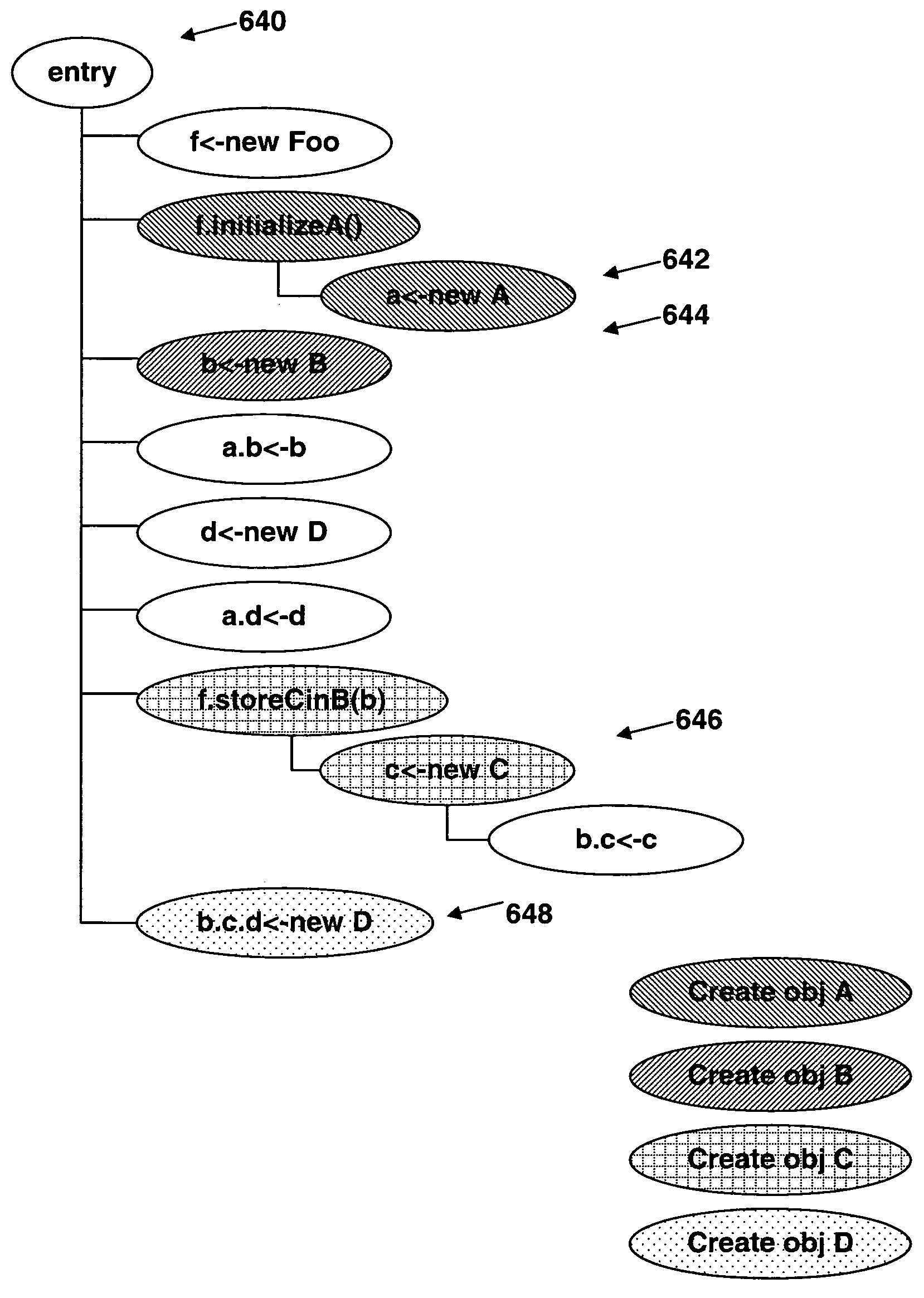
The present invention provides a method, apparatus, and computer instructions for program analysis. This involves loading a target program onto a data processing system and using software to determine its hierarchies in the form of control flow and containment information. This information can be presented to a user in a related and selected format, such as a program and GUI. The technical effect of this invention is to provide a better understanding of the structure and behavior of programs, which can aid in the development and testing of new programs.

Problems solved by technology

A key problem with program analysis tools is how to present complex information about a program to an end user.
While program understanding tools are valuable to software developers, testers and administrators in providing insights into the inner workings of what can be complex applications, current approaches for communicating this information are incomplete, often leaving the end-user an with insufficient understanding of the program.
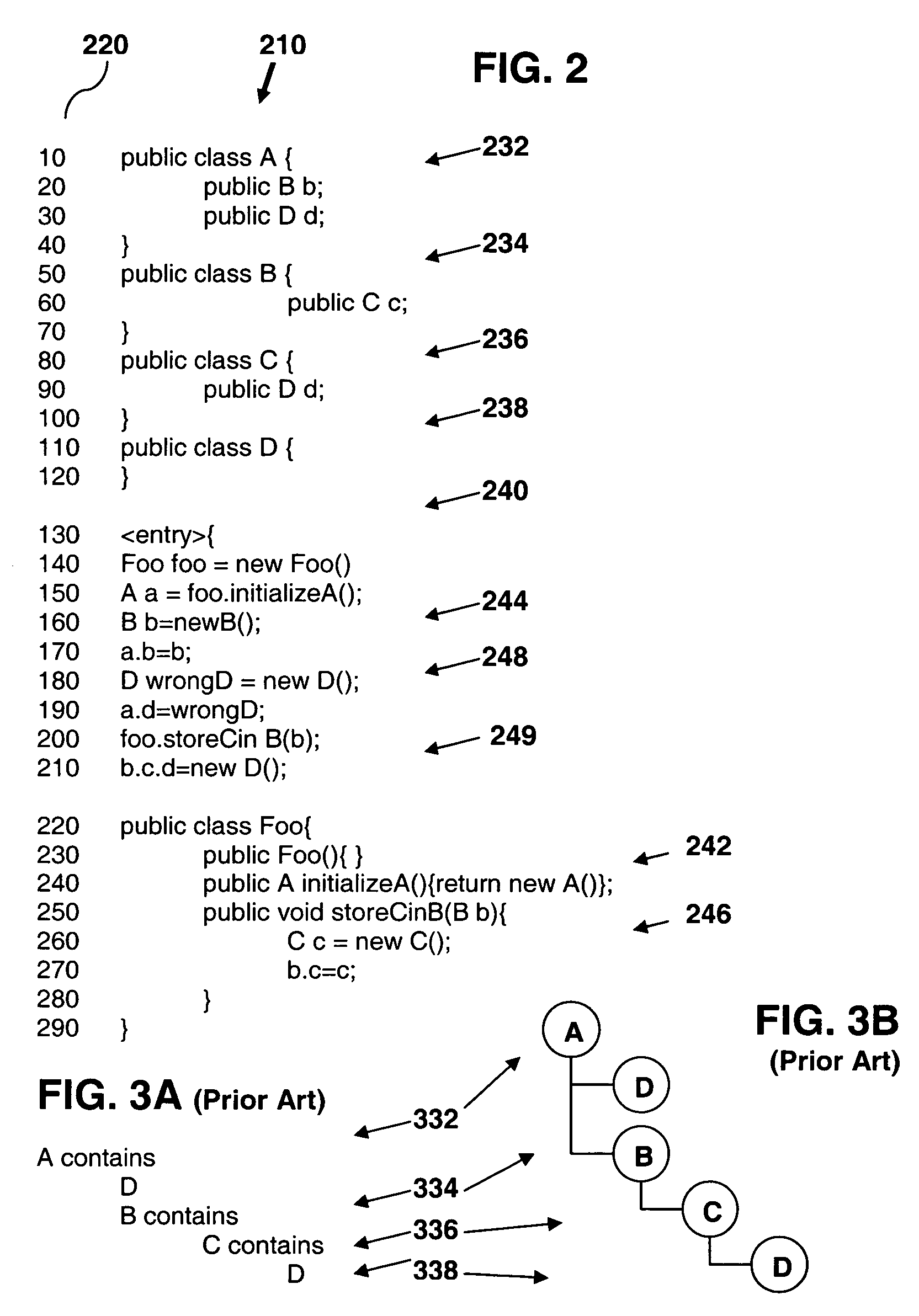
For most program analysis processes, the information provided by just one of these two groups of hierarchical representations is of limited value.
The chain of events causing the unexpected behavior may be difficult to uncover even with a slow, careful stepping through the program.
Again, the object containment representation fails to give the user and adequate understanding of the program.

Method used


Image

  • Program analysis tool presenting object containment and temporal flow information
  • Program analysis tool presenting object containment and temporal flow information
  • Program analysis tool presenting object containment and temporal flow information

Examples


Embodiment Construction

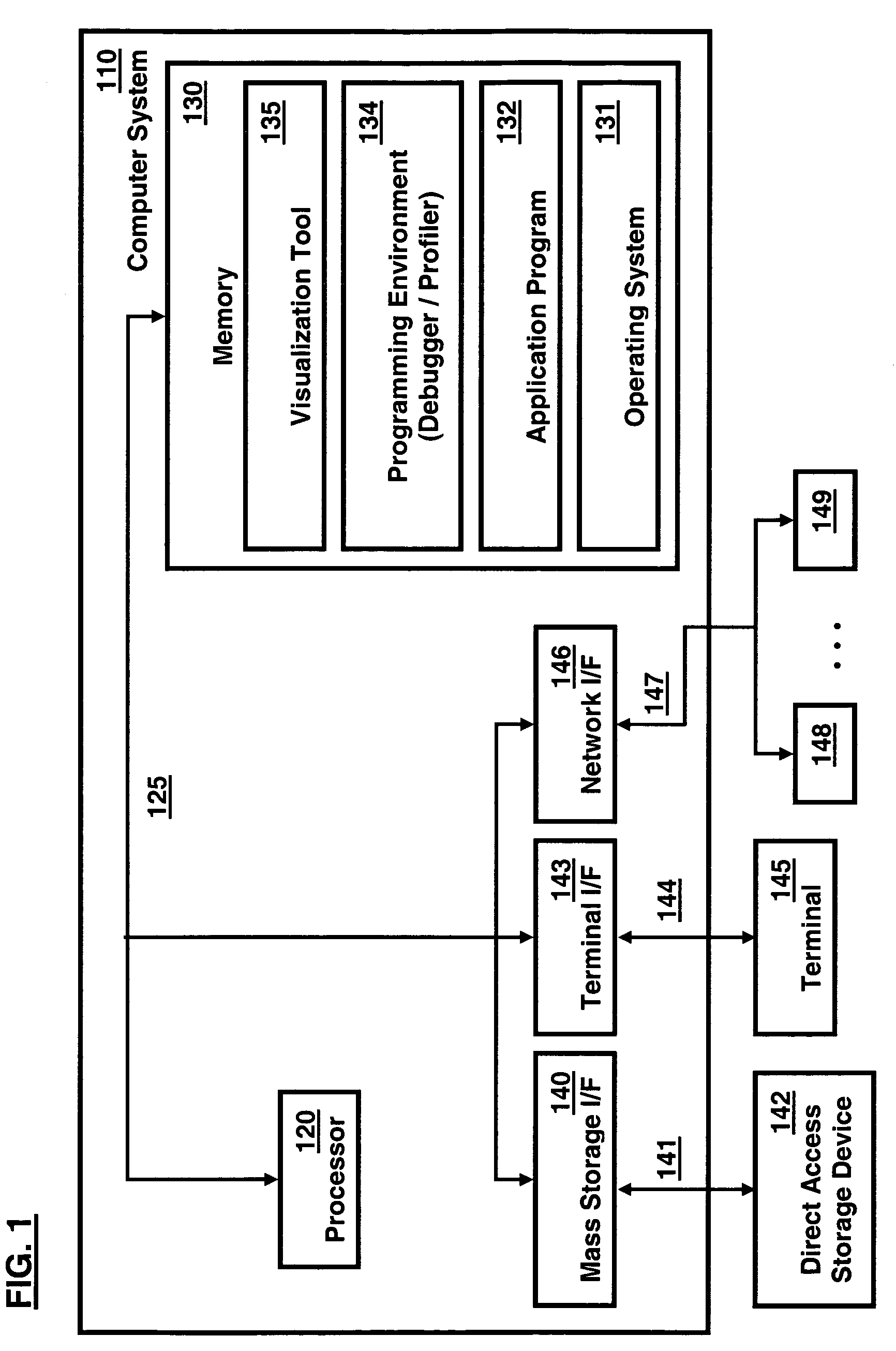
[0019]With reference now to the figures and in particular with reference to FIG. 1, a pictorial representation of an information processing system in which the present invention may be implemented is depicted in accordance with certain presently preferred embodiments of the invention. In general, the routines which are executed when implementing these embodiments, whether implemented as part of an operating system or a specific application, component, program, object, module or sequence of instructions, will be referred to herein as computer programs, or simply programs. The computer programs typically comprise one or more instructions that are resident at various times in various memory and storage devices in an information processing or handling system such as a computer, and that, when read and executed by one or more processors, cause that system to perform the steps necessary to execute steps or elements embodying the various aspects of the invention.

[0020]A particular informat...


PUM


Abstract

The present invention provides a method, apparatus, and computer instructions for program analysis. In an exemplary embodiment, a target program is loaded onto a data processing system including a program analysis software component. Hierarchies in the form of control flow and containment information about the target program are determined, using either static or dynamic, and direct (e.g., instrumented profilers) or indirect (e.g., monitored runtime), processing techniques, depending on the application and program analysis tool being used. The control flow and object containment information are then presented in a related and selected format for consideration by a user. One embodiment includes a program and GUI (graphical user interface) operably providing control flow-annotated object containment hierarchies to a user, the hierarchies including control flow, allocation and storage information added to object containment information.

Description

TECHNICAL FIELD[0001]The invention disclosed generally relates to computers and computer software. More specifically, the invention is generally related to program analysis tools.BACKGROUND OF THE INVENTION[0002]The increasing complexity of software programs has led to the development of a variety of tools to aid programmers and administrators in understanding the structure and functionality of their programs. Examples of these program analysis tools include debuggers, runtime execution visualizers, development environments and software quality tools. A debugger is a program that interactively traces the logic flow of a program and the contents of memory elements to locate, analyze, and correct bugs in another computer program. Runtime execution tools like profilers use processes like sampling or direct instrumentation to obtain a variety of runtime information, such as heavy memory allocation sites, CPU usage hot-spots, unnecessary object retention, and monitor contention, for a co...

Claims


Application Information

Patent Timeline
Patent Type & Authority Patents(United States)
IPC IPC(8): G06F9/44
CPCG06F11/3604
Inventor REIMER, DARRELL CHRISTOPHERSRINIVAS, KAVITHA
Owner INT BUSINESS MASCH CORP
Learn More