Watch-winding apparatus

a watch-winding and automatic technology, applied in the direction of electric winding, instruments, horology, etc., can solve the problems of cushion holder difficult to be pulled out, drawer things to fall out, and the most part of input energy and time is not most efficien

Inactive Publication Date: 2009-05-12
HERO TEAM CORP
View PDF4 Cites 30 Cited by
  • Summary
  • Abstract
  • Description
  • Claims
  • Application Information

AI Technical Summary

Benefits of technology

[0014]3. A tab is now added to the spring cushion for easy removal of the cushion.

Problems solved by technology

The prior art generally still may have one or more of the following deficiencies:1. Since the indicating system is too simple, the user can not know what program and in what status the automatic watch-winding is now operating.2. Since the watch is placed and revolved in a form not perfectly simulating a human wrist, the most part of input energy as well as the time are not most efficient.3. Since there is no handle or any tab on the cushion holder, the cushion holder is difficult to be pulled out.4. Since the whole apparatus is portable, the drawer automatically slides open when the apparatus is being handled from one place to another, which might cause things in the drawer to fall out.5. Since heavy watches may be placed on the winding cup, the slipping device may cause the cup to slip.

Method used


Image

  • Watch-winding apparatus
  • Watch-winding apparatus
  • Watch-winding apparatus

Examples


Embodiment Construction

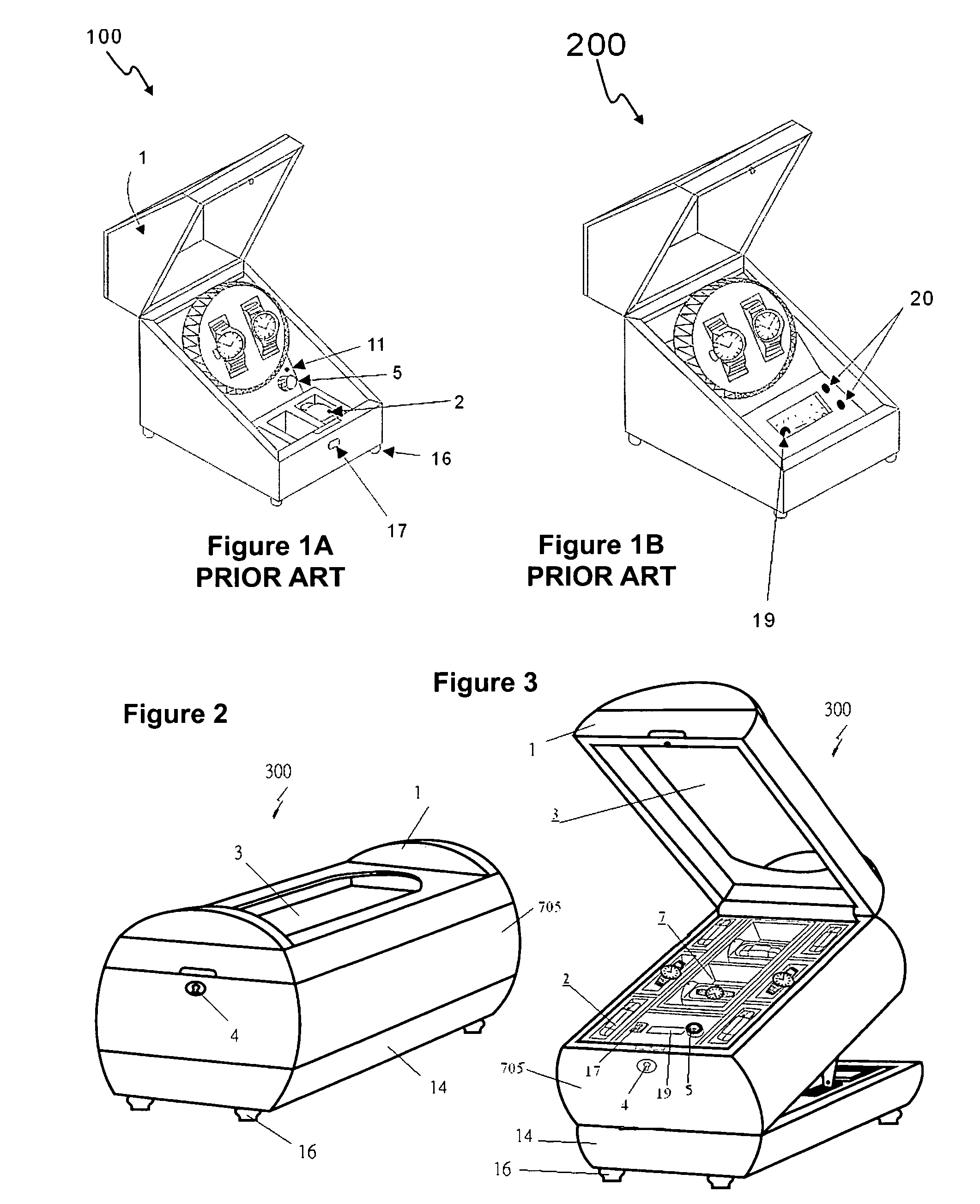
[0061]With reference to FIG. 1, there are two prior art watch-winders 100 and 200 disclosed in U.S. application Ser. No. 10 / 895,528 filed Jul. 21, 2004. Watch-winder 100 only has a knob 5 and an LED 11 for selecting the program. When the knob 5 is turned some angle, and a symbol on the knob 5 is just under the LED 11, the program (represented by said symbol) is selected. Though watch-winder 200 has a LCD panel 19 and two push-buttons 20, they perform the same function of the knob 5 and the LED 11 of 100.

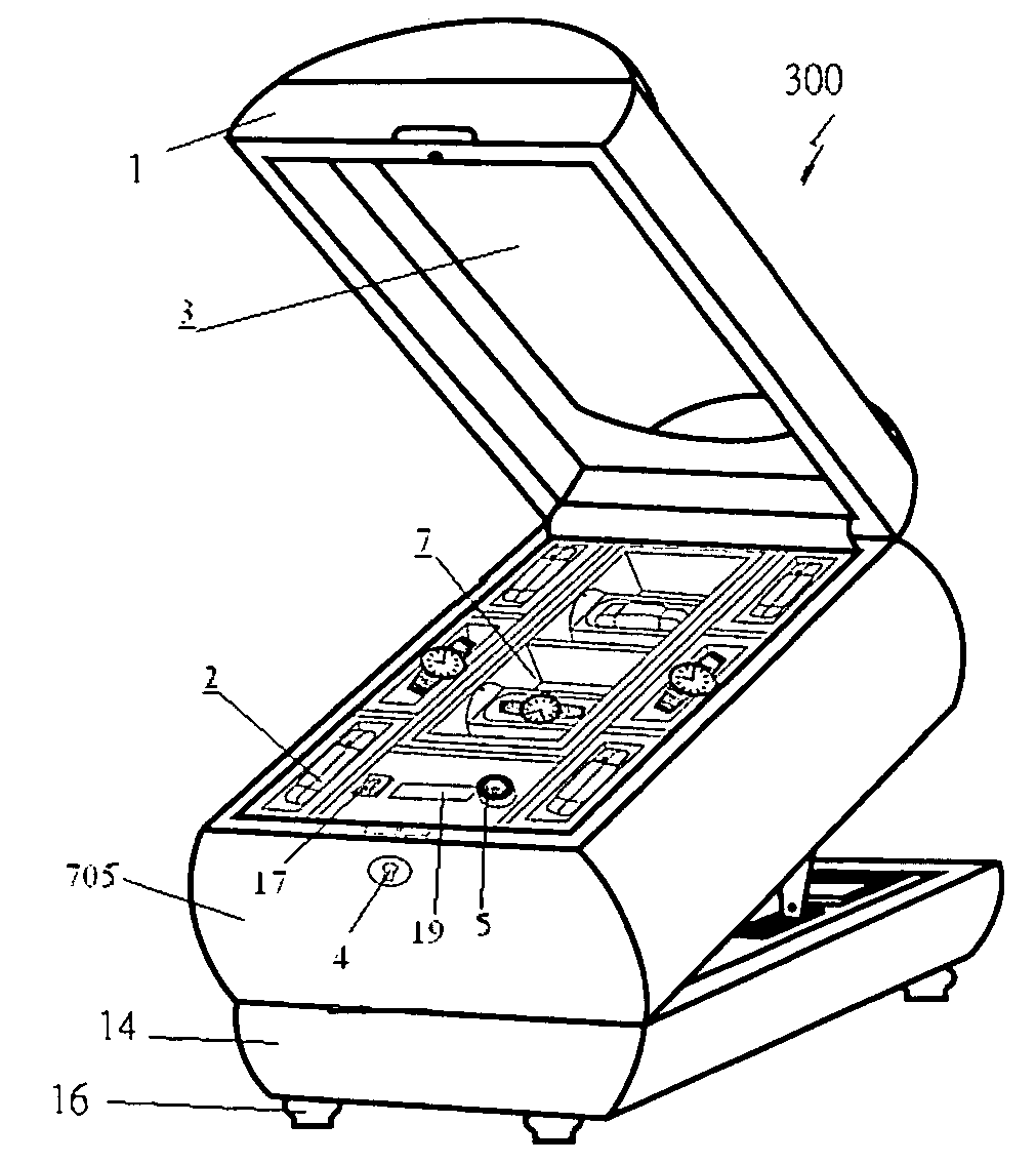
[0062]With reference to FIGS. 2 and 3, a perspective view of a new designed watch winder is shown with a normal analog function rotator dial in a closed status. FIG. 3 is a perspective view of the watch-winder with a LCD screen and a function rotator dial, in an operating status. In both FIG. 2 and FIG. 3, watch-winder 300 has a lid 1, a plurality of the self-adjustable watch cushion holders 2, a glass window 3, a lock 4, a knob 5 for selecting program, two rotating trays 7 for windi...


PUM


Abstract

An improved watch-winding apparatus comprising: a bottom support; a body; a lid cover with a glass window; and a plurality of tabbed spring cushions. A solid direct drive system drives the rotating tray. An electronic system keeps the rotating tray swinging per the intended program. Where a drawer is employed, a catch lock mechanism is also provided to prevent the drawer from automatically sliding open.

Description

CROSS-REFERENCE TO RELATED APPLICATION[0001]This application is a continuation-in-part of U.S. patent application Ser. No. 11 / 326,786 filed Jan. 6, 2006.FIELD OF THE INVENTION[0002]This invention relates to a watch-winding apparatus, particularly to the improvement of an automatic watch-winding apparatus.BACKGROUND OF THE INVENTION[0003]Automatic watch-winding apparatus have been developed for decades. Therefore, there are many different kinds of automatic watch-winding apparatus for self-winding watches in the market nowadays. An advanced prior art of this kind is disclosed in U.S. application Ser. No. 10 / 895,528 filed Jul. 21, 2004 which was invented by the same inventor of this invention.[0004]The prior art generally still may have one or more of the following deficiencies:[0005]1. Since the indicating system is too simple, the user can not know what program and in what status the automatic watch-winding is now operating.[0006]2. Since the watch is placed and revolved in a form n...

Claims


Application Information

Patent Timeline
Patent Type & Authority Patents(United States)
IPC IPC(8): G04B3/00G04C1/04
CPCG04D7/009
Inventor LOUIE, LIP MAN
Owner HERO TEAM CORP
Why Eureka
Try Eureka