Connector EMI shielding structure

Active Publication Date: 2009-05-12
ALL BEST ELECTRONICS
View PDF2 Cites 31 Cited by
  • Summary
  • Abstract
  • Description
  • Claims
  • Application Information

AI Technical Summary

Benefits of technology

[0004]It is therefore a primary object of the present invention to provide an improved connector EMI shielding structure tha

Problems solved by technology

Thus, the conventional connector EMI shielding structure requires a lot of complicated manufacturing pro

Method used


Image

  • Connector EMI shielding structure
  • Connector EMI shielding structure
  • Connector EMI shielding structure

Examples


Embodiment Construction

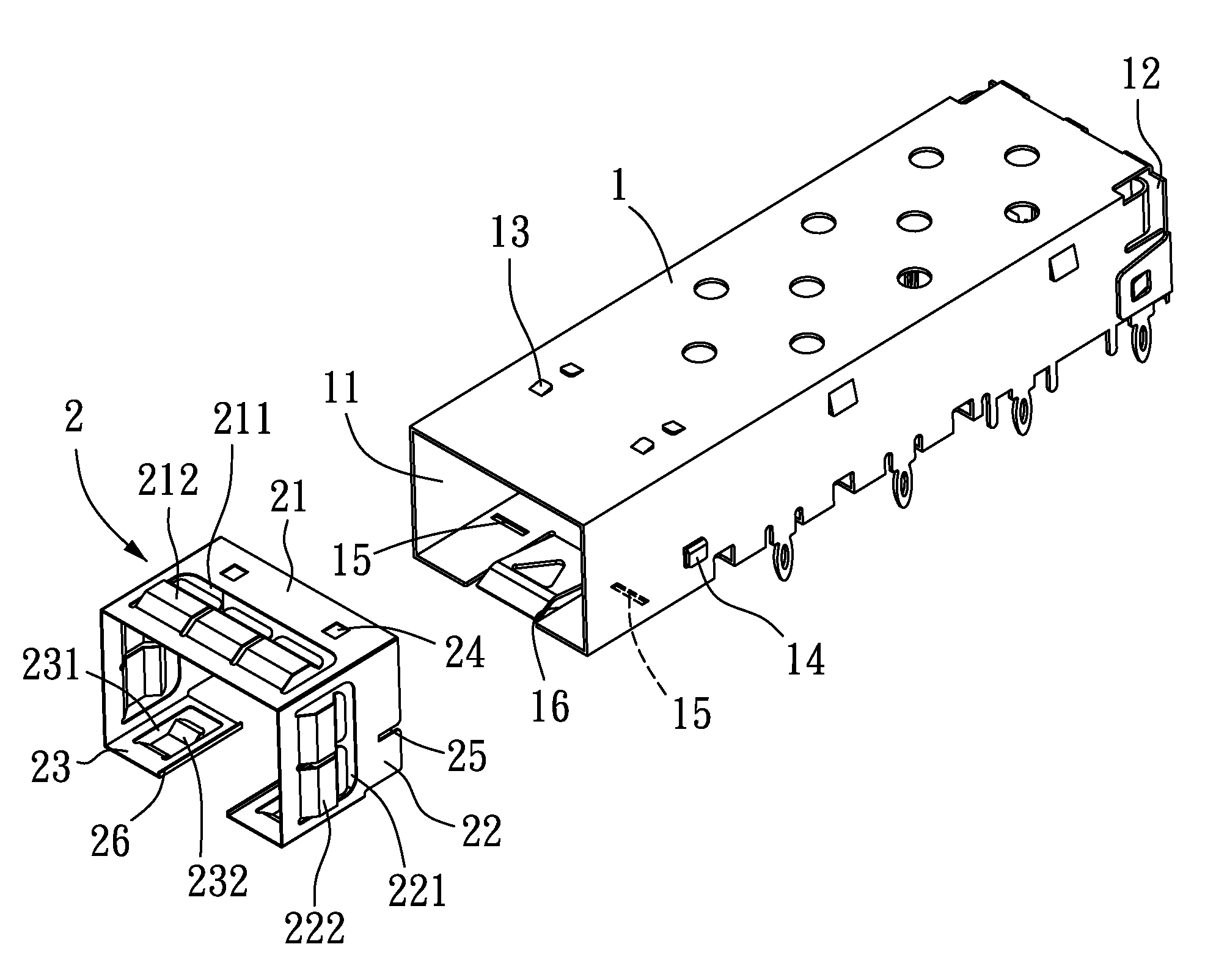
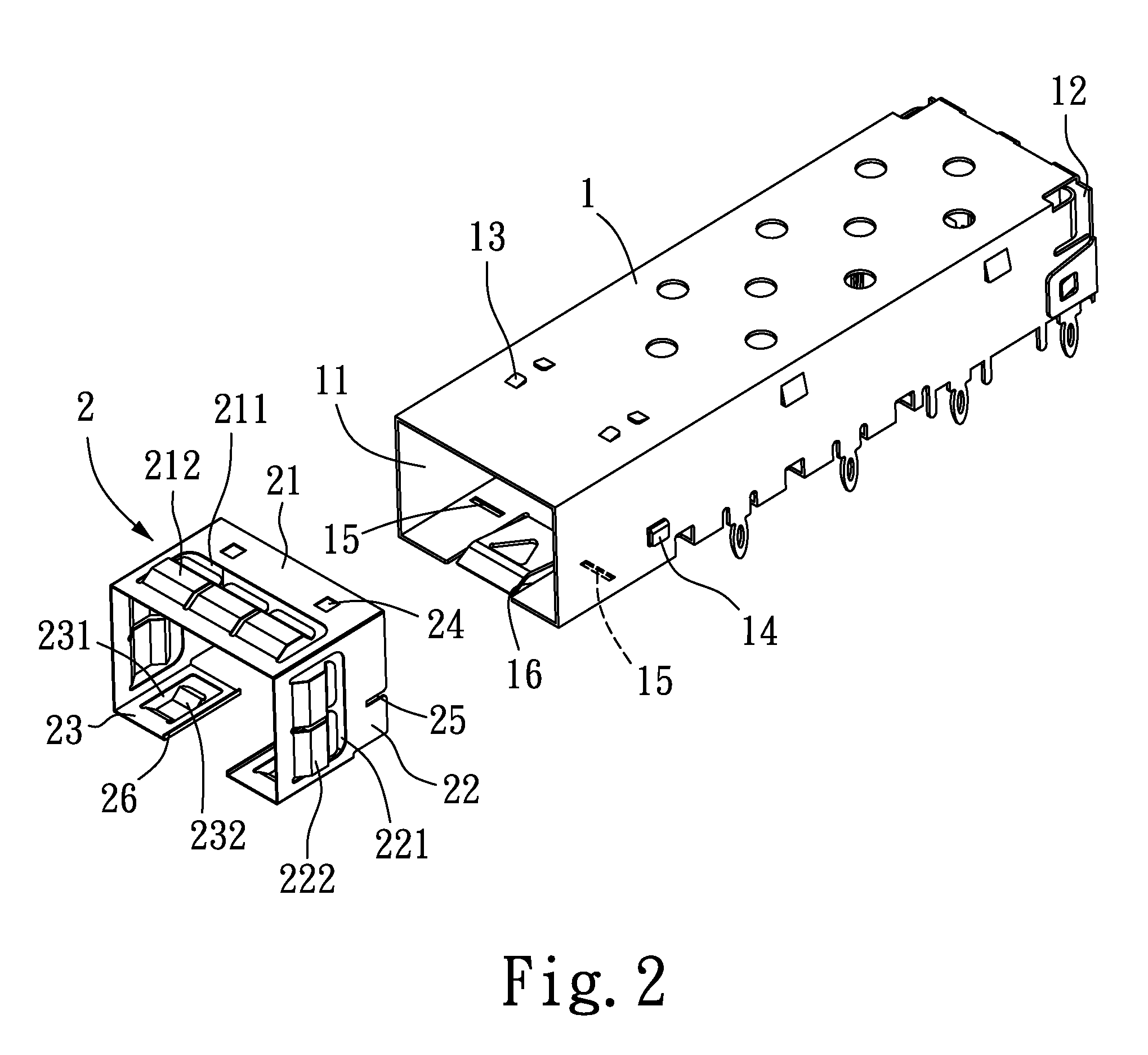
[0012]Please refer to FIGS. 2 and 3 that are exploded and assembled perspective views, respectively, of a connector electromagnetic interference (EMI) shielding structure according to a preferred embodiment of the present invention. As shown, the connector EMI shielding structure of the present invention includes an enclosure 1 and a shielding unit 2.

[0013]The enclosure 1 has a front open end 11 and a rear end closed by a back plate 12, and is provided on a top wall with at least two tongues 13, on two sidewalls with a bent hook 14 each, on a bottom wall with at least two retaining sections 15, and on the bottom wall near the two retaining sections 15 with a slit 16 each.

[0014]The shielding unit 2 is fitted around the front open end 11 of the enclosure 1, and includes a top panel 21, two side panels 22 perpendicularly downward extended from two lateral edges of the top panel 21, and two bottom panels 23 horizontally extended from two lower edges of the two side panels 22 toward each...


PUM


Abstract

A connector EMI shielding structure includes an enclosure having a front open end and a rear end closed by a back plate, and being provided on two sidewalls with a bent hook each; and a shielding unit for fitting around the front open end of the enclosure. The shielding unit includes a top panel, two side panels, and two bottom panels. Each of the top panel, the side panels, and the bottom panels of the shielding unit is formed with an opening, from an inner edge of which one or more elastic leaves are extended rearward for elastically pressing against the enclosure. And, each of the side panels of the shielding unit is provided on a rear edge with a cut for engaging with the bent hooks on the sidewalls of the enclosure. With these arrangements, the shielding unit can be easily and firmly assembled to the enclosure.

Description

FIELD OF THE INVENTION[0001]The present invention relates to a connector electromagnetic interference (EMI) shielding structure, and more particularly to a connector EMI shielding structure that can be easily and firmly assembled for use.BACKGROUND OF THE INVENTION[0002]FIG. 1 shows a conventional connector electromagnetic interference (EMI) shielding structure. As shown, the conventional connector EMI shielding structure includes an enclosure 3 and three shielding elements 4 for mounting to an upper side and two lateral sides of an open end of the enclosure 3. Each of the shielding elements 4 includes a connecting section 41 and a plurality of elastic leaves 42 extended from two opposite sides of the connecting section 41. To assemble the shielding elements 4 to the enclosure 3, first connect the three shielding elements 4 at the connecting sections 41 to the upper, the left, and the right side of the open end of the enclosure 3, respectively; and then spot-weld the connecting sect...

Claims


Application Information

Patent Timeline
IPC IPC(8): H01R13/648
CPCG02B6/4201H01R13/65802H05K9/0058G02B6/3825G02B6/4292G02B6/4277H01R13/6582
Inventor YANG, HAVEN
Owner ALL BEST ELECTRONICS
Why Eureka
Try Eureka