Optical resin film and polarizing film and liquid crystal display device using the same

a technology of optical resin film and polarizing plate, which is applied in the direction of optics, polarising elements, instruments, etc., can solve the problems of severe requirements for viewing angle dependence of liquid crystal display device, and the inability to meet requirements, and achieve high contrast ratio

Active Publication Date: 2009-05-12
FUJIFILM CORP
View PDF10 Cites 4 Cited by
  • Summary
  • Abstract
  • Description
  • Claims
  • Application Information

AI Technical Summary

Benefits of technology

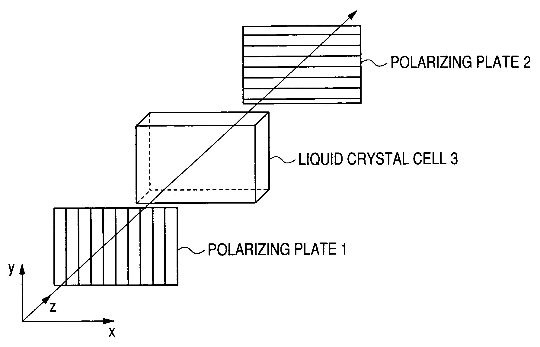
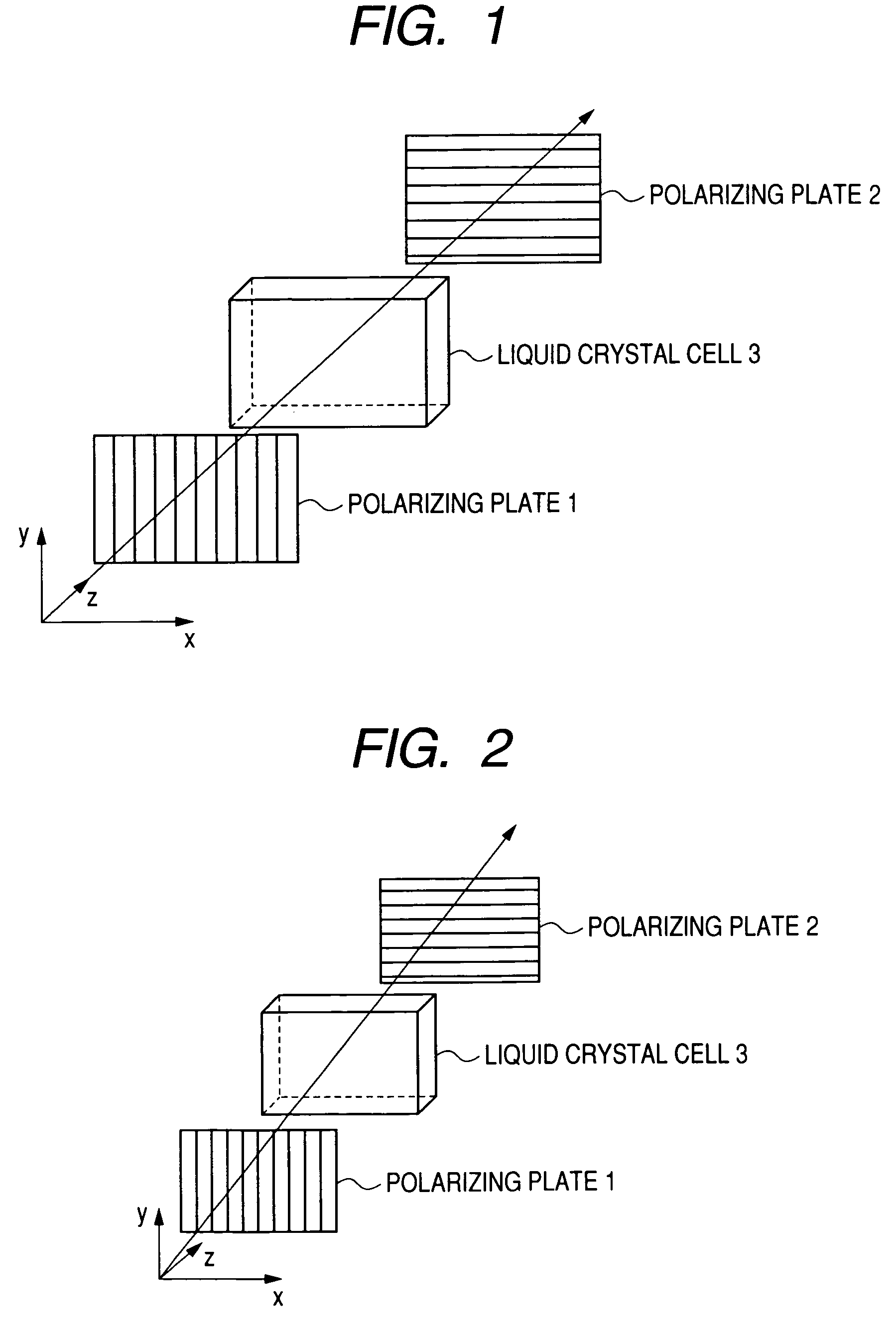
[0039]The effect of the invention will be described in connection with the attached drawings. FIG. 1 is a diagrammatic view illustrating the configuration of an ordinary VA mode liquid crystal display device. A VA mode liquid crystal display device comprises a liquid crystal cell 3 having a liquid crystal layer which causes liquid crystal molecules to align vertically with respect to the surface of the substrate when no voltage is applied thereto, i.e., during black display and polarizing plates 1 and 2 aligned with the liquid crystal cell 3 interposed therebetween and their transmission axes (shown by the stripes in FIG. 1) disposed perpendicular to each other. In FIG. 1, light is incident on the liquid crystal display device on the polarizing plate 1 side thereof. When light propagating in the direction normal to the surface of the polarizing plate 1, i.e., z axis direction is incident on the liquid crystal display device, the light beam transmitted by the polarizing plate 1 passes through the liquid crystal cell 3 while being linearly polarized, and then is fully blocked by the polarizing plate 2. As a result, an image having a high contrast can be displayed.
[0040]As shown in FIG. 2, however, oblique incidence of light behaves unlike the normal incidence. Light which is incident on the liquid crystal display device in an oblique direction which is not z axis direction, i.e., direction oblique to the polarizing direction of the polarizing plates 1 and 2 (so-called OFF AXIS), is affected by an oblique retardation to show a change of polarization when it is transmitted by the vertically aligned liquid crystal layer of the liquid crystal cell 3. Further, the apparent transmission axis of the polarizing plates 1 and 2 are deviated from perpendicular alignment. Due to the two causes, light incident in the oblique direction in OFF AXIS cannot be fully blocked by the polarizing plate 2, causing light leakage during black display and hence contrast drop.
[0041]The polar angle and the azimuthal angle will be defined as follows. The polar angle is the angle of tilt from the direction normal to the surface of the film, i.e., z axis in FIGS. 1 and 2. For example, the direction normal to the surface of the film has a polar angle of 0°. The azimuthal angle indicates the direction of the line rotated clockwise from the positive direction of x axis. For example, the positive direction of x axis has an azimuthal angle of 0°. The positive direction of y axis has an azimuthal direction of 90°. The aforementioned oblique directions in OFF AXIS mainly include those having a polar angle which is not 0° and an azimuthal angle of 45°, 135°, 225° and 315°.
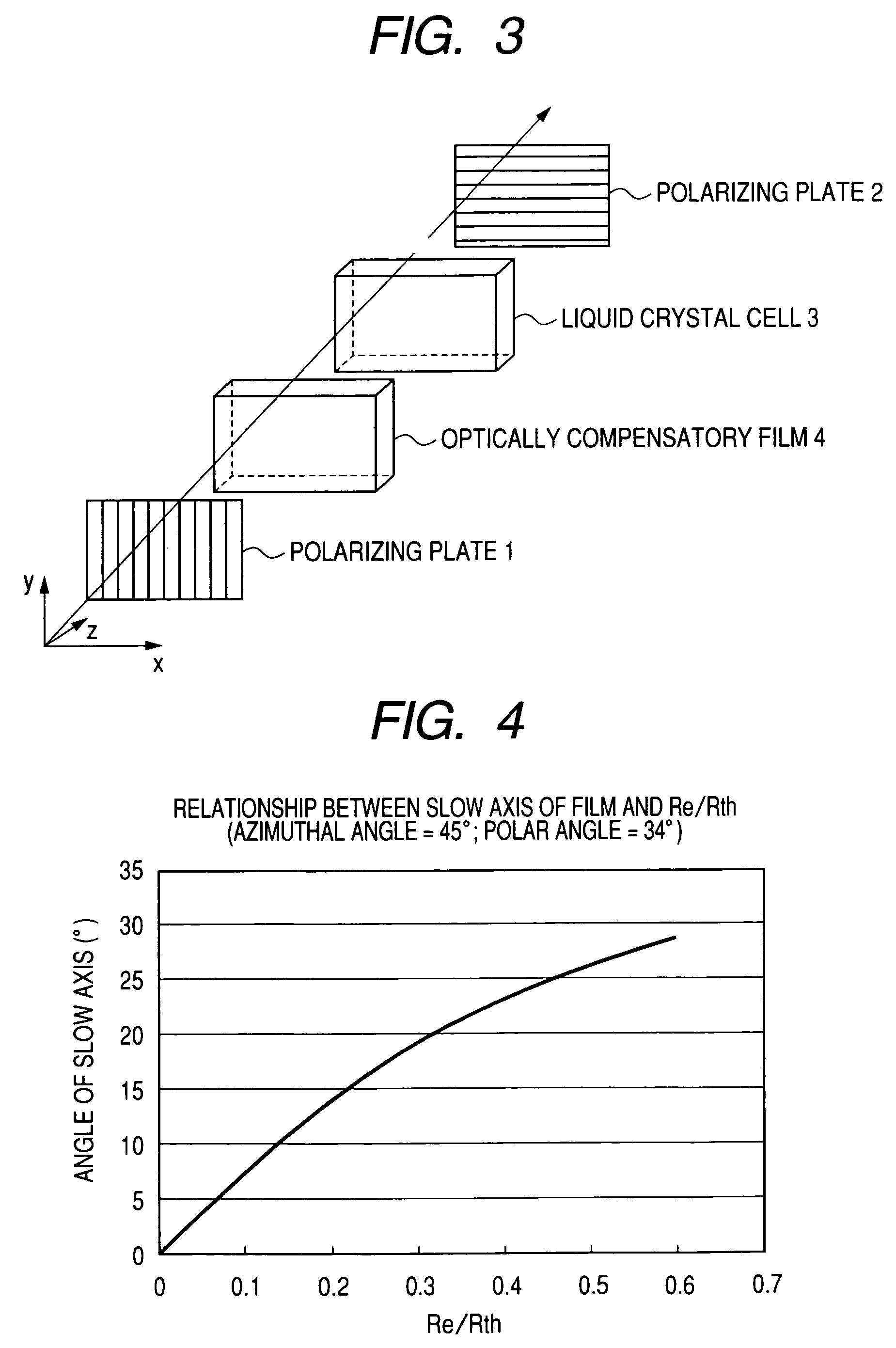
[0042]FIG. 3 depicts a diagrammatic view of an example of configuration for illustrating the effect of the invention. The configuration of FIG. 3 is the same as that of FIG. 1 except that an optical resin film (hereinafter also referred to as “optically compensatory film”) 4 is provided interposed between the liquid crystal cell 3 and the polarizing plate 1. As previously mentioned, the optically compensatory film 4 satisfies the following relationships:
[0047]In accordance with the invention, the use of an optically compensatory film having the aforementioned optical properties makes it possible to optically compensate R, G and B light which are incident obliquely with slow axis and retardation which vary with wavelength. As a result, as compared with the related art liquid crystal display devices, the viewing angle contrast during black display can be drastically improved and the coloration in the viewing direction during black display can be drastically eliminated. In the specification, the wavelength of R, G and B light are 650 nm, 550 nm and 450 nm, respectively. The wavelength of R, G and B light are not necessarily represented by these values. However, these wavelength values are thought to be suitable for the definition of optical properties by which the effect of the invention can be exerted.
[0048]In the invention, Re / Rth, which is the ratio of Re to Rth, is particularly noted. This is because the value of Re / Rth determines the two intrinsic polarizing axes along which light propagates through a biaxial birefringent medium in oblique direction. FIG. 4 depicts an example of the result of calculation of the relationship between the direction of one of the two intrinsic polarizing axes and Re / Rth developed when light is obliquely incident on the optically compensatory film to be used in the invention. In this calculation, it is supposed that the direction of propagation of light is at an azimuthal angle of 45° and a polar angle of 34°. As can be seen in the results shown in FIG. 4, once Re / Rth is determined, one of the intrinsic polarizing axes is determined. How the incident light changes in its polarization as it passes through the optically compensatory film is mainly determined by the orientation of the in-plane slow axis of the optically compensatory film and the retardation of the optically compensatory film. In the invention, Re / Rth relationship is defined for R, G and B wavelengths to optimize both the in-plane slow axis and retardation, which are factors that mainly determine the change of polarization, for R, G and B wavelengths. As a result, even when there are two factors, i.e., effect of oblique retardation of liquid crystal layer on obliquely incident light and deviation of apparent transmission axis of polarizing plates 1 and 2, complete compensation by one optically compensatory film is allowed, making it possible to eliminate contrast drop. This means that when the parameter of the film is determined with R, G and B representing all the visible light ranges, substantially complete compensation can be made over the entire visible light range.

Problems solved by technology

However, liquid crystal display devices for TV use which are supposed to give a wide screen image that can be viewed at various angles have severe requirements for dependence on viewing angle.
These requirements cannot be met even by the aforementioned approach.
Despite its capability of attaining substantially full black display in the direction along the line normal to panel, VA mode liquid crystal display devices have been disadvantageous in that when the panel is viewed in oblique direction, light leakage occurs, causing the reduction of viewing angle.
However, these approaches merely allow the elimination of light leakage with respect to a certain wavelength range (e.g., green light in the vicinity of 550 nm) but don't take into account light leakage in other wavelength ranges (e.g., blue light in the vicinity of 450 nm, red light in the vicinity of 650 nm).

Method used


Image

  • Optical resin film and polarizing film and liquid crystal display device using the same
  • Optical resin film and polarizing film and liquid crystal display device using the same
  • Optical resin film and polarizing film and liquid crystal display device using the same

Examples


example 1

(Preparation of Cellulose Acylate Film)

[0476]A mixture obtained by uniformly stirring 100 parts by mass of cellulose made from linter pulp and glacial acetic acid in an amount of 100 parts by mass based on the mass of cellulose was added to a chilled mixture of 245 parts by mass of acetic anhydride, 365 parts by mass of acetic acid and 15 parts by mass of sulfuric acid as a catalyst in a reaction vessel where they were then subjected to acetylation at 47° C. for 60 minutes. During the termination of acetylation reaction, 45.5 parts by mass of an aqueous solution of magnesium acetate (30 mass-%) for hydrolyzation and neutralization was added to the reaction mixture so that the excess acetic anhydride and sulfuric acid were subjected to hydrolyzation and neutralization, respectively. Thereafter, to the reaction solution was added about 12.8 parts by mass of an aqueous solution of magnesium acetate (30 mass-%) for ripening while being heated to 60° C. Thereafter, to the reaction soluti...

example 2

[0497]A film was prepared in the same manner as in Example 1 except that the film thickness was changed as set forth in Table 2. A liquid crystal television was prepared from the film in the same manner as in Example 1. The liquid crystal television thus prepared was then evaluated for color shift under varying environmental conditions set forth in Table 2. In some detail, the liquid crystal TV was allowed to stand under the environmental conditions (temperature / relative humidity) set forth in Table 2 for 12 hours, and then measured for color shift. The results are set forth in Table 2 below.

[0498]

TABLE 2Example 2[Re[Re(450) / (650) / RthRth(450)] / (650)] / ReRe[Re[Re(450) / (650) / (550) / (550) / FilmColor shiftFilmReReReRthRthRthReReRthRththickness(25° C.)No.(450)(550)(650)(450)(550)(650)(550)(550)(550)](550)](μm)60%10%80%Remarks215562691751701650.891.110.861.157010010398Invent.225562691751701650.891.110.861.15100115125123Compar.235562691751701650.891.110.861.155010110399Invent.Color shift is r...

example 3

[0500]A 1.0 N solution of potassium hydroxide (solvent: water / isopropyl alcohol / propylene glycol=69.2 parts by mass / 15 parts by mass / 15.8 parts by mass) was spread over the film prepared in Example 1 on the band side thereof at a rate of 10 cc / m2. The coated film was then kept at about 40° C. for 30 seconds. The alkaline solution was scratched off the coat film. The coated film was washed with purified water. Water droplets were then blown off the coated film with air from an air knife. Thereafter, the coated film was dried at 100° C. for 15 seconds. The film thus processed was then measured for contact angle with respect to purified water. The result was 42°.

(Preparation of Alignment Film)

[0501]A alignment film coating solution having the following formulation was spread over each of Film Nos. 1 to 3 at a rate of 28 ml / m2 using a #16 wire bar coater. The coated films were each dried with 60° C. hot air for 60 seconds and then with 90° C. hot air for 150 seconds to prepare an alignm...


PUM

PropertyMeasurementUnit
thicknessaaaaaaaaaa
wavelength rangesaaaaaaaaaa

Abstract

An optical resin film, which has Re (λ) and Rth (λ) satisfying retardation requirements (A) to (D), and has a thickness of from 30 μm to 80 μm: (A) 0.1<Re (450) / Re (550)<0.95 (B) 1.03<Re (650) / Re (550)<1.93 (C) 0.4<(Re / Rth (450)) / (Re / Rth (550)))<0.95 (D) 1.05<(Re / Rth (650) / (Re / Rth (550))<1.9, and a polarizing plate and a liquid crystal display device using the optical resin film.

Description

BACKGROUND OF THE INVENTION[0001]1. Field of the Invention[0002]The present invention relates to an optical resin film and a polarizing plate and a liquid crystal display device comprising same.[0003]2. Description of the Related Art[0004]Liquid crystal display devices have been widely used for monitor for personal computer and cellular phone, television, etc. because they are advantageous in that they can operate at low voltage with low power consumption and are available in small size and thickness. These liquid crystal display devices have been proposed in various modes depending on the alignment of liquid crystal molecules in the liquid crystal cell. To date, TN mode, in which liquid crystal molecules are aligned twisted at about 90 degrees from the lower substrate to the upper substrate of the liquid crystal cell, has been a mainstream.[0005]A liquid crystal display device normally comprises a liquid crystal cell, an optical compensation sheet and a polarizer. The optical compe...

Claims


Application Information

Patent Timeline
Patent Type & Authority Patents(United States)
IPC IPC(8): G02F1/1335G02B5/30
CPCG02F1/133528G02F1/13363G02F2001/133635G02F2202/40G02F2413/04G02F1/133635
Inventor MARUYAMA, YOICHISAITOH, YUKITOHISAKADO, YOSHIAKISUGIYAMA, SUSUMU
Owner FUJIFILM CORP
Why Eureka
Try Eureka