Apparatus and method for electrostatically charging fluid drops

a technology of electrostatic charging and fluid drop, which is applied in the field of fluid inkjet printing, can solve the problems of inability to use high-resolution (500 dpi or greater) electrostatic inkjet systems, high-resolution versions of continuous inkjet printers, and inability to accurately place tubes or channels into support structures

Active Publication Date: 2009-05-19
EASTMAN KODAK CO
View PDF23 Cites 4 Cited by
  • Summary
  • Abstract
  • Description
  • Claims
  • Application Information

AI Technical Summary

Problems solved by technology

However, the accurate placement of the tubes or channels into a support structure and then electrically connecting such devices to a signal source was both difficult and time consuming especially in multi-jet systems utilizing hundreds of individual streams of ink drops spaced only a few thousandths of an inch apart.
The spatial requirements of these prior art systems make them unsuitable for use in of state of the art high-resolution (i.e. 500 dpi or greater) electrostatic inkjet systems.
However, high-resolution versions of these continuous inkjet printers, especially those requiring multiple rows of closely spaced nozzles, are however subject to undesirable electrostatic challenges when electrostatic drop charging and separation architectures are employed.
However, when closely spaced nozzle arrays as required by a high-resolution print-head are considered, effective charge coupling between any given charge electrode and its respective drop stream may not be enough to ensure minimal charge variations among the charged drops.
The tight spatial requirements of high-resolution CIJ print-heads can lead to undesirable charge variations caused by indirect electrostatic effects between neighboring charge electrodes and a given drop stream.
Print drop charge variation will affect print quality by affecting the drop placement accuracy on the recording surface.
Charge variation in drops not selected for printing, will affect the ability to effectively gutter and recycle the unprinted ink, impacting the reliability of the print-head.
Poor print quality can thus offset the gains in higher print image resolution.
Poor print quality can occur when drops that are intended to remain uncharged, or are intended to have some specific amount of charge, actually have additional charge induced by the charge electrodes of adjacent or nearby nozzles.
Unlike prior art charge electrodes that completely surrounded their associated drop streams, planar electrodes by their design, cannot easily do this.
Consequently, the shielding effects that prior art tunnel charge electrodes provided between adjacent nozzles is not readily provided by planar electrodes, thus increasing the occurrence of nozzle-to-nozzle crosstalk effects.
In addition to nozzle-to-nozzle crosstalk effects, other undesired electrostatic crosstalk effects can manifest themselves within a high-resolution CIJ printer.
When drop-to-drop cross talk does occur within a given drop stream, a drop currently being charged may have its resulting charge adversely influenced by charge distortions created by the electric fields of preceding adjacent drops.
These additional electric fields may prevent a specific drop from being charged with the correct charge level and thus lead to additional print quality issues.
Additionally, charge compensation schemes have further been proposed to minimize electrostatic crosstalk effects that give rise to non-optimal print drop placement.
These approaches are suitable for low-density print-heads, but for state-of-the-art systems with high-resolutions and hundreds or thousands of nozzles per print-head, these methods become expensive.
As previously stated, drop trajectories can also be additionally adversely affected by aerodynamic effects.
As further print resolution improvements are required and nozzle structures are manufactured using micromachining methods, it is clear that there remain challenges when designing high-resolution continuous inkjet systems requiring superlative drop placement accuracy.

Method used


Image

  • Apparatus and method for electrostatically charging fluid drops
  • Apparatus and method for electrostatically charging fluid drops
  • Apparatus and method for electrostatically charging fluid drops

Examples


Embodiment Construction

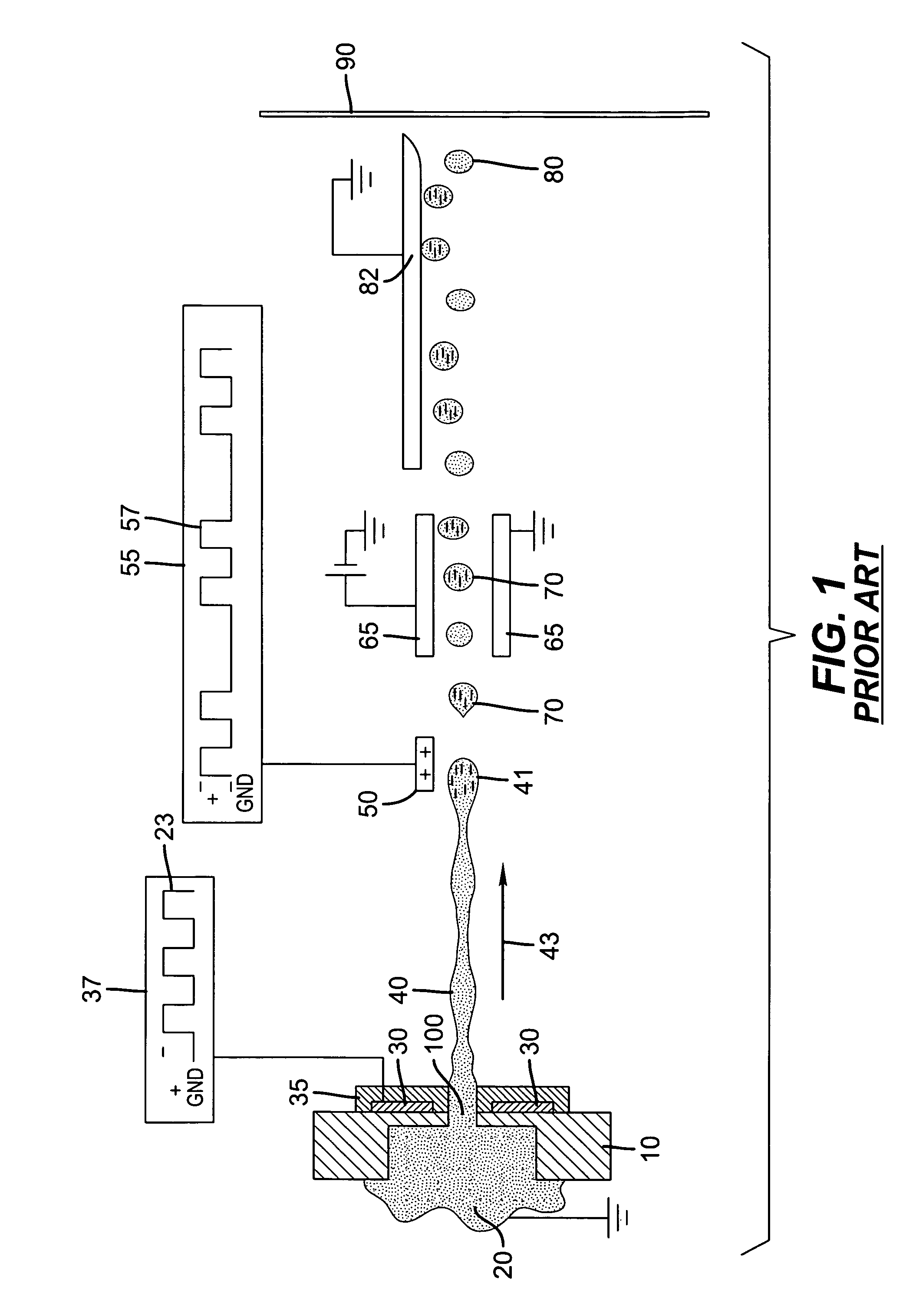
[0063]FIG. 1 shows a conventional prior art electrostatic continuous inkjet (CIJ) printer used to excite a continuous jet of conductive fluid into a stream of drops. Fluid manifold 10 contains conductive fluid 20 that is forced under pressure through nozzle 100 in the form of a jet 40 that is emitted in jetting direction 43. Conductive fluid 20 is grounded or otherwise connected through an electrical pathway. Jet 40 can be stimulated in a variety of ways to produce a corresponding stream of drops. These stimulation methods can include vibrating nozzle 100. Alternatively, a second stimulation method involves electrohydrodynamically (EHD) exciting jet 40 with an EHD exciter. A third technique, which has frequently been employed in the prior art, is to impose a pressure variation on the fluid in the nozzle 100 by means of a piezoelectric transducer placed typically within a cavity feeding the nozzle. In the prior art system shown in FIG. 1, an EHD stimulation electrode 30 is employed. ...


PUM


Abstract

A continuous printing apparatus includes a printhead including a first row of nozzles and a second row of nozzles. The first row of nozzles are spaced apart from the second row of nozzles by a distance A. The nozzles of the first row and the nozzles of the second row have a nozzle to nozzle spacing B when compared to each other. The apparatus includes a plurality of charging electrodes with one of the plurality of charging electrodes corresponding to each of the nozzles of the first row and the second row, wherein A≧B / 2. The apparatus can include a first deflection electrode and a second deflection electrode with the first deflection electrode being spaced apart from the second deflection electrode by a distance D, wherein D>A.

Description

CROSS REFERENCE TO RELATED APPLICATIONS[0001]This is a 111A application of Provisional Application Ser. No. 60 / 658,571 filed Mar. 7, 2005.FIELD OF THE INVENTION[0002]The invention pertains to the field of ink-jetting of fluids and, in particular, to construction of a high-resolution CIJ head for use in continuous inkjet systems.BACKGROUND OF THE INVENTION[0003]The use of ink jet printers for printing information on a recording media is well established. Printers employed for this purpose may be grouped into those that use a continuous stream of fluid drops and those that emit drops only when corresponding information is to be printed. The former group is generally known as continuous inkjet printers and the latter as drop-on-demand inkjet printers. The general principles of operation of both of these groups of printers are very well recorded. Drop-on-demand inkjet printers have become the predominant type of printer for use in home computing systems, while continuous inkjet systems ...

Claims


Application Information

Patent Timeline
Patent Type & Authority Patents(United States)
IPC IPC(8): B41J2/06
CPCB41J2/085B41J2/09
Inventor STEINER, THOMAS W.
Owner EASTMAN KODAK CO
Why Eureka
Try Eureka