
Earth anchor

a technology of earth anchors and pivoting anchors, applied in mining structures, construction, foundation engineering, etc., can solve the problems of increased force necessary to pivot and lock anchors, difficult to drive into, and higher driving force, so as to improve the drivability, improve the drivability, and improve the straight line drive tendency

Active Publication Date: 2009-05-19
MACLEAN POWER LLC
View PDF12 Cites 26 Cited by
  • Summary
  • Abstract
  • Description
  • Claims
  • Application Information

AI Technical Summary

Benefits of technology

[0012]It is therefore an object of this invention to provide a ground anchor having improved drivability requiring the use of minimal drive force and having improved straight line drive tendencies.
[0013]It is a further object of this invention to provide a substantially cylindrical or tubular or ground anchor of the pivoting type having improved drivability provided by projecting surfaces extending at an angle to one another projecting forwardly of the main body of the anchor a distance of between 20 and 40% of the overall length of the anchor when measured from the leading end of the main body portion or 10 to 20% of the overall length of the anchor when measured from the end of a transition zone between the end of the main body portion and the projecting surfaces, where the transition zone consists of an axially progressive diameter reduction from an outer diameter of the main body portion to the projecting surfaces, and where the projecting surfaces terminate in leading edges which are pointed or chiseled and which comprise a plurality of leading edge sections which are axially and radially offset from one another in a stepwise fashion, the projecting surfaces having generally flat opposite side surfaces which resist rotation of the anchor about its axis during driving.
[0014]It is another object of this invention to provide a generally cylindrical, oval or rectangular body ground anchor having a leading edge defined by chiseled surfaces which are spaced axially and radially from one another and which are formed at the leading edges of generally flat plates projecting forward of the main body portion, the plates being positioned at an angle to one another, and the main body portion having ribs running substantially the length of the main body portion on opposite sides thereof, the ribs having non-blunt leading edges and generally having a width measured outwardly from the surface of the main body portion of about 20% or less of the transverse width of the main body portion whereby the ribs act to assist in straight driving of the anchor without providing significant drag or resistance to rotation.

Problems solved by technology

Such anchors have included plate anchors such as shown in U.S. Pat. No. 3,969,854, which are generally difficult to drive into the ground.
However, the presence of the wings can, in certain instances, can be disadvantageous in that: (a) they provide a much larger area which must be pushed through the ground during insertion of the anchor thereby requiring a higher driving force; and (b) due to their rather large lateral extent with respect to the central body, the force necessary to pivot and lock the anchor is considerably increased.
Additionally, (c) the wings can cause a deflection of the anchor during driving.
This can not only result in a mispositioned anchor, it can cause a bending of the drive rod, and in extreme conditions can prevent or hinder withdrawal of the drive rod after the anchor has been placed.
While this serration or stepping of the leading edges of large wing anchors is an improvement over prior large wing anchors, the necessity for a higher driving force and the difficulties associated with rotation to the locked position remain a problem.
The use, however, of cylindrical anchors, with their cruciform driving edges leaves the anchor, during driving, at risk of wandering or deviating from a straight path.
Since such anchors are normally driven into the ground at an angle to the vertical, which will represent the angle of the application of load after setting of the anchor, and since the load application is generally at an angle other than 90 degrees, particularly where the anchor is used to anchor a guide wire, a fence end or tree support or the like, it is sometimes difficult to drive the anchor straight.

Method used


Image

  • Earth anchor
  • Earth anchor
  • Earth anchor

Examples


Embodiment Construction

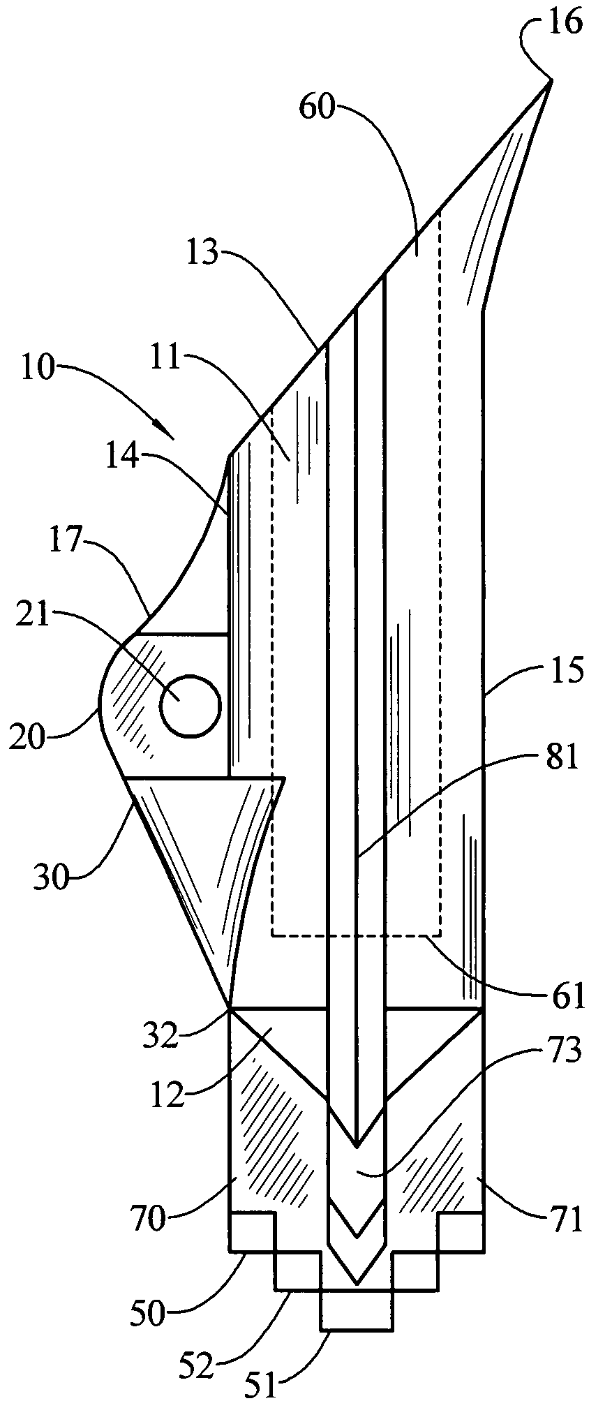
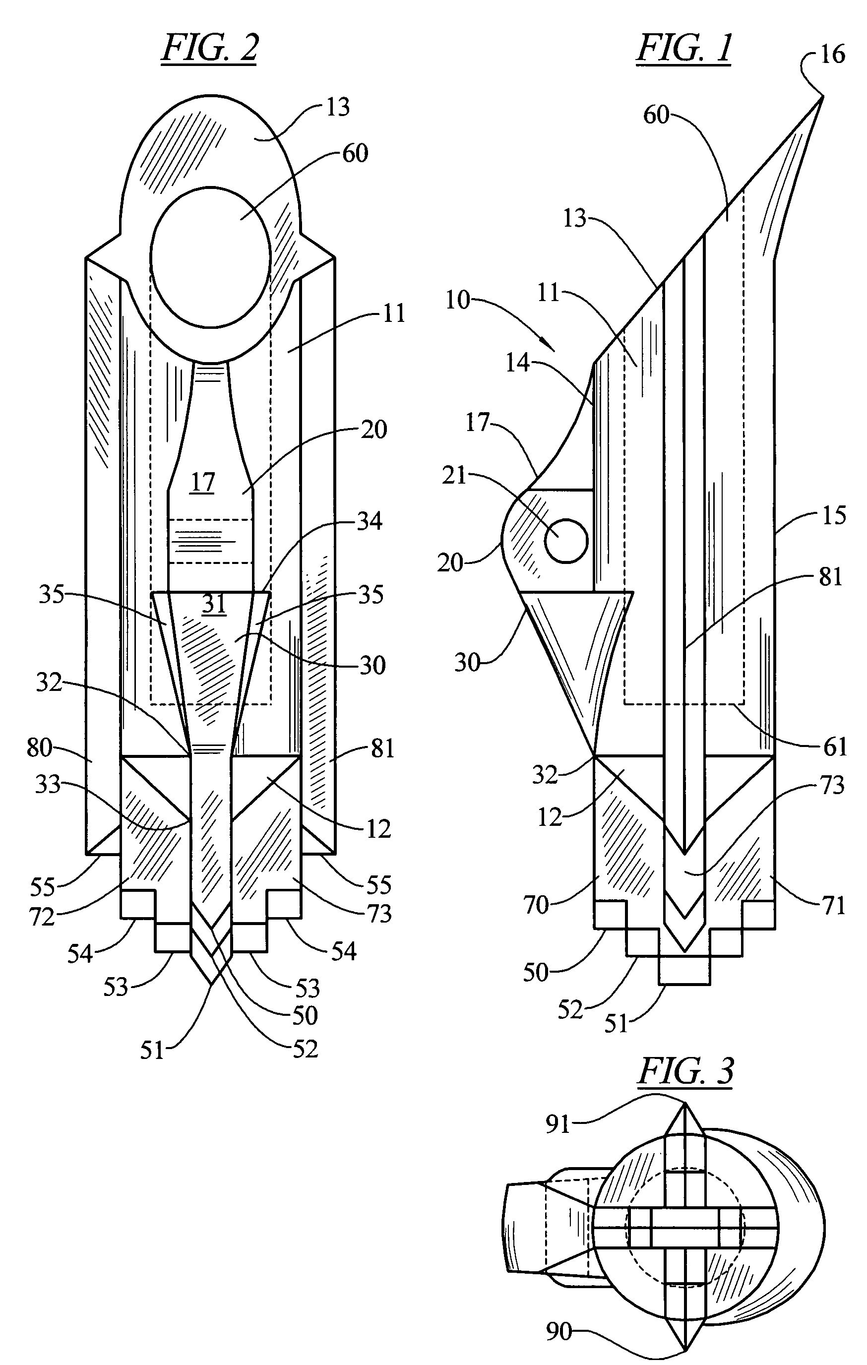
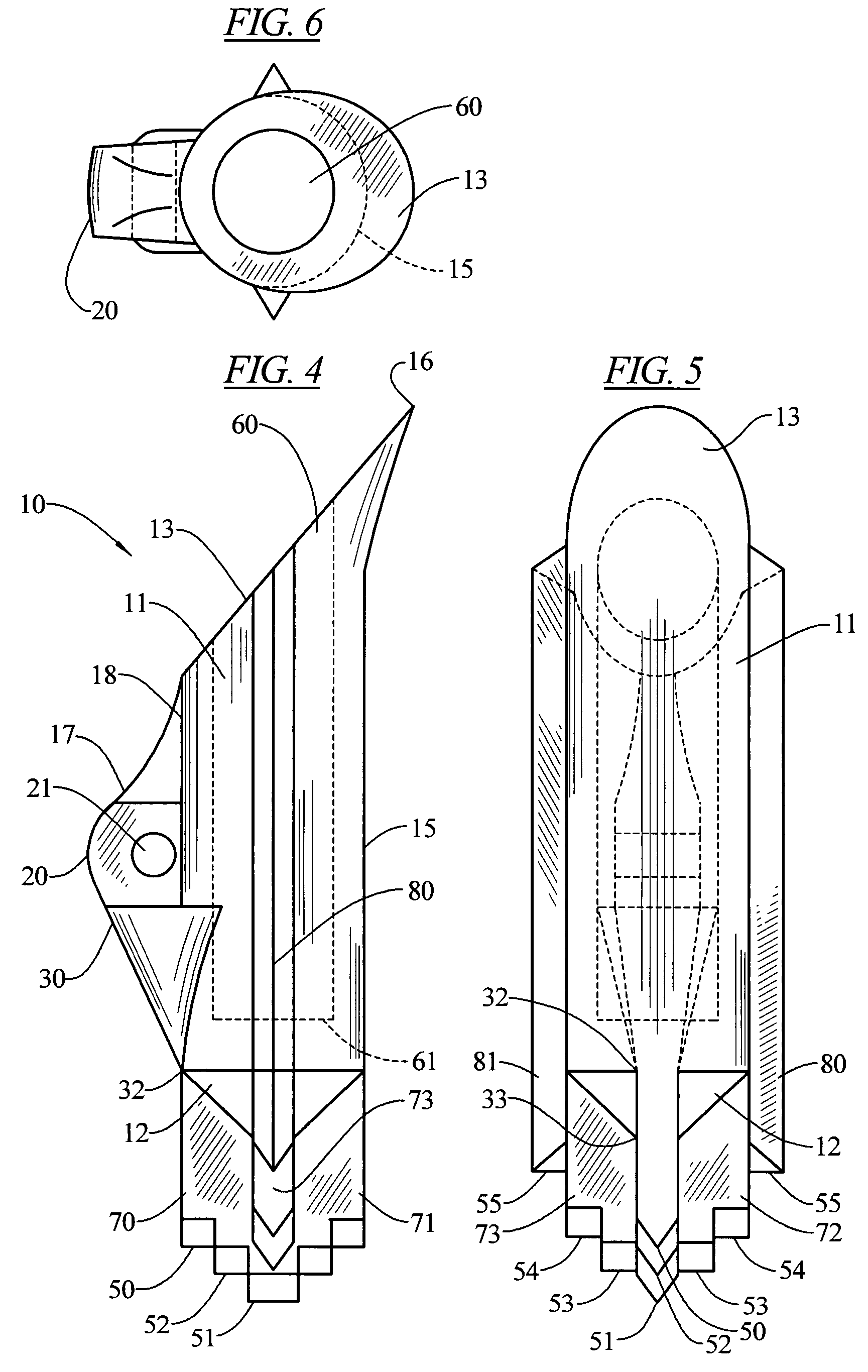
[0023]As shown in FIGS. 1 and 2, the anchor 10 of this invention consists of a generally cylindrical main body portion 11 which may have a generally conical leading end 12 and a trailing end 13 formed at an oblique angle to the longitudinal axis of the main body. The trailing end 13 incorporates at a bottom 15 of main body 11 an outturned lip 16 which will bite into the soil surrounding the anchor after it has been driven to its desired depth and a withdrawal load is applied. A rib 17 is formed on a top 18 of the main body 11, and in the embodiment illustrated, includes a projecting central section 20 projecting furthest from the top 18 of any portion of the main body, that section 20 being provided with an opening 21 extending transversely therethrough.

[0024]The opening may have a cable threaded through it and clamped back on itself or may provide a fixture point for a shackle to which a cable or a rod may be attached. Numerous other fixture examples for attaching the anchor wire o...


PUM


Abstract

An earth anchor of the pivoting type having an essentially cylindrical body, a blind bore extending therein to from a trailing axial end of the cylindrical body and a leading edge projecting from a leading end of the body, the leading edge chisel shaped for ease of penetration into the ground, guiding surfaces extending substantially normal to the leading edge and forward of the main body portion, the guiding surfaces having a plurality of leading chisel edges stepped back from the leading edge and from one another as the guiding surface leading edges are spaced further away from a center of the leading edge, the guiding surfaces terminating in final leading edge spaced axially from the leading edge and laterally from each of the stepped leading edges and having at least a portion which extend radially beyond the main body, guide ridges extending from the final leading edges to the trailing axial end projecting radially from the body substantially no further than the maximum width of the guiding surface leading edges.

Description

RELATED APPLICATIONS[0001]Applicant hereby claims priority of co-pending Design application No.: 29 / 270,187 filed Dec. 19, 2006.BACKGROUND OF THE INVENTION[0002]1. Field of the Invention[0003]This invention relates to ground anchors, more specifically to pivoting ground anchors.[0004]2. General Background[0005]Ground anchors or earth anchors of the pivoting or tilting type are well known and generally include a main body portion having a leading edge adapted to be forced into the ground, a trailing edge including an outturned lip and a cable or guide wire attachment point intermediate the leading and trailing edges generally positioned from about the mid point of the overall length of the anchor or towards the trailing edge so that upon exerting a force on the cable or attached guide wire after insertion of the anchor into the ground, the trailing edge outturned lip will bite into the earth causing the anchor to rotate or pivot to a locked position generally at a right angle to the ...

Claims


Application Information

Patent Timeline
Patent Type & Authority Patents(United States)
IPC IPC(8): E02D5/80
CPCE02D5/80
Inventor STAHM, WILLIAM G.
Owner MACLEAN POWER LLC
Learn More