
Walking assisting device

a technology of assisting device and walking aid, which is applied in the field of walking assisting device, can solve the problems of increasing the cost and total weight of the leg link, and achieve the effects of preventing the extension speed of the extensible, free bending, and reducing the flexion angl

Active Publication Date: 2009-05-19
HONDA MOTOR CO LTD
View PDF5 Cites 4 Cited by
  • Summary
  • Abstract
  • Description
  • Claims
  • Application Information

AI Technical Summary

Benefits of technology

Enables comfortable and controlled operation of the walking assisting device with the leg link extended straight, maintaining controllability and reducing user discomfort by preventing loss of extension speed at zero flexion angle, while minimizing cost and weight increases.

Problems solved by technology

This, however, increases the cost and the total weight of the leg link due to the effect of the driving source for extension and retraction.

Method used


Image

  • Walking assisting device
  • Walking assisting device
  • Walking assisting device

Examples


Embodiment Construction

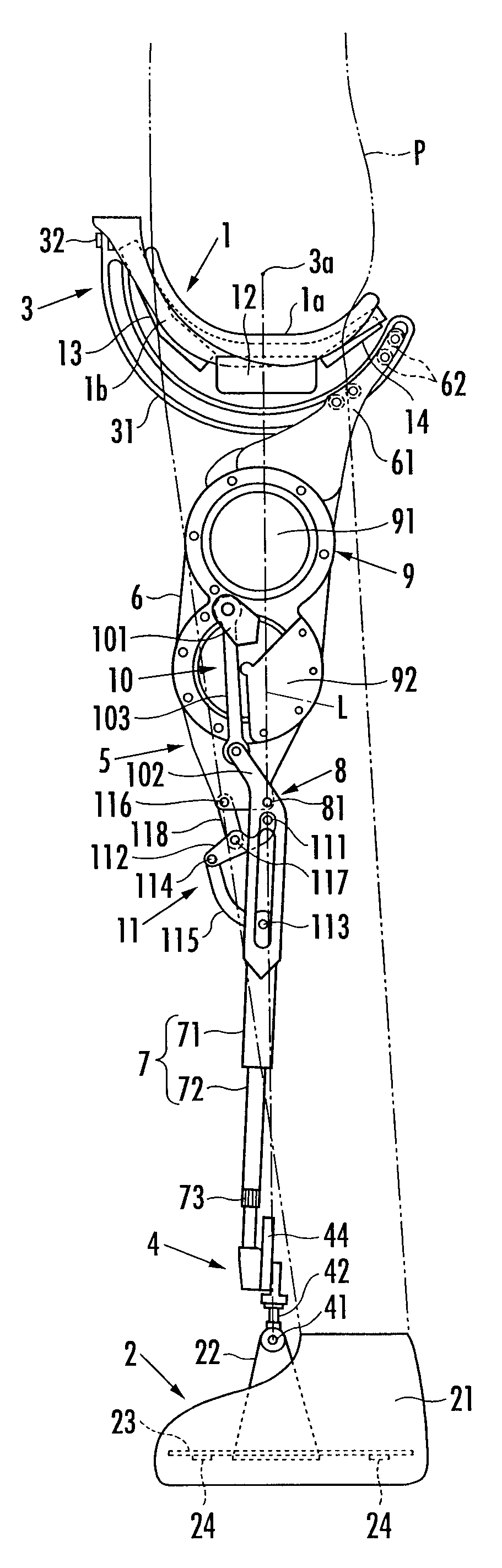
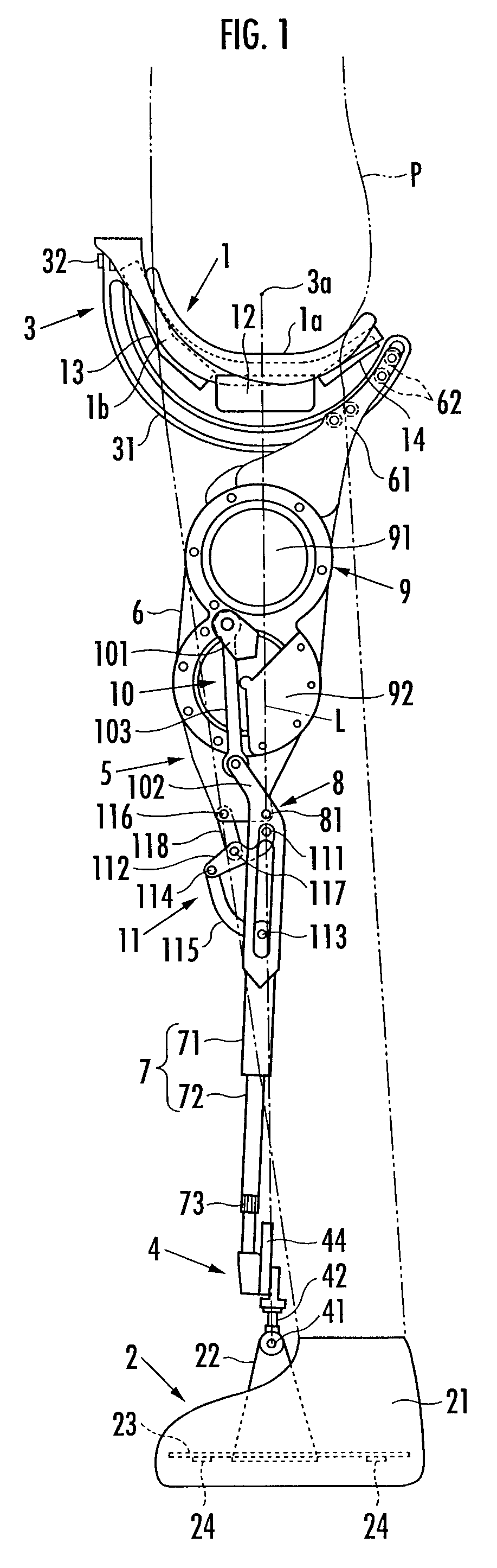
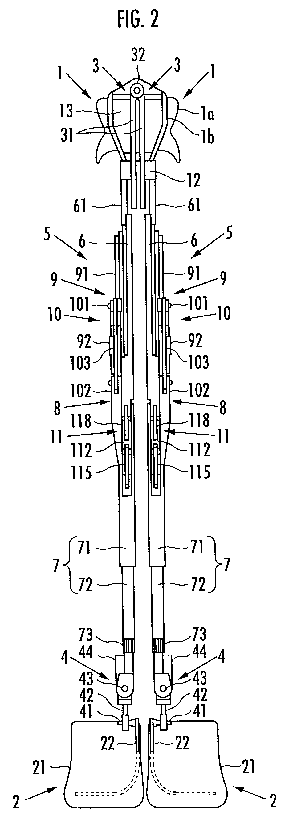
[0021]A walking assisting device according to embodiments of the present invention will now be described hereinafter. As shown in FIG. 1 and FIG. 2, the walking assisting device includes a seat member 1 which is a load transfer portion which a user P sits astride, a pair of left and right foot attachment portions 2, 2 which are attached to user's left and right feet, and a pair of left and right leg links 5, 5 which are connected to the seat member 1 each via a first joint portion 3 located at the upper end and connected to the two foot attachment portions 2, 2 each via a second joint portion 4 located at the lower end.

[0022]Each leg link 5 is composed of a freely bending and stretching link which varies a distance between the first joint portion 3 and the second joint portion 4. More specifically, each leg link 5 includes an upper first link 6 connected to the seat member 1 via the first joint portion 3 and a lower second link 7 connected to each foot attachment portion 2 via a sec...


PUM


Abstract

A walking assisting device that transmits a force generated by a leg link to a user's trunk via a load transfer portion. The leg link includes a first link connected to the load transfer portion via a first joint portion, a second link connected to a foot attachment portion via a second joint portion, a third joint portion which connects the first link to the second link so as to be free to bend and stretch, and a driving source which drives the third joint portion. Even if a flexion angle of the third joint portion reaches zero degree, the controllability is maintained in the direction of pushing up the load transfer portion so that the leg link can be extended straight with the user's leg extended straight. An interlock system retracts and extends the second link and increases and decreases the flexion angle of the third joint portion.

Description

BACKGROUND OF THE INVENTION[0001]1. Field of the Invention[0002]The present invention relates to a walking assisting device for assisting a user in walking.[0003]2. Description of the Related Art[0004]Conventionally, as with this type of walking assisting device, there is known a trunk attachment portion attached to the user's trunk, a thigh attachment portion attached to a thigh of a user's leg with being connected to the trunk attachment portion via a hip joint portion corresponding to a human hip joint, a crus attachment portion attached to the crus of the user's leg with being connected to the thigh attachment portion via a knee joint portion corresponding to a human knee joint, and a foot attachment portion attached to a user's foot with being connected to the crus attachment portion via an ankle joint portion corresponding to a human ankle joint. Driving sources which drive the joint portions are provided coaxially with the joint portions, respectively (refer to Japanese Paten...

Claims


Application Information

Patent Timeline
Patent Type & Authority Patents(United States)
IPC IPC(8): A61F5/00
CPCA61F5/0102A61H3/008A63B23/047A61H2201/5053A61H2201/165A61H2205/10A61H2205/12
Inventor HIKI, YUTAKA
Owner HONDA MOTOR CO LTD
Learn More