Magnetic resonance imaging apparatus and magnetic resonance imaging method
a magnetic resonance imaging and magnetic resonance imaging technology, applied in the direction of magnetic measurements, instruments, measurement devices, etc., can solve the problems of difficult realization of multichannel, small degree of flexibility in selection, complicated selection circuit, etc., and achieve the effect of suppressing degradation and shortening the stab
- Summary
- Abstract
- Description
- Claims
- Application Information
AI Technical Summary
Problems solved by technology
Method used
Image

Examples
first embodiment
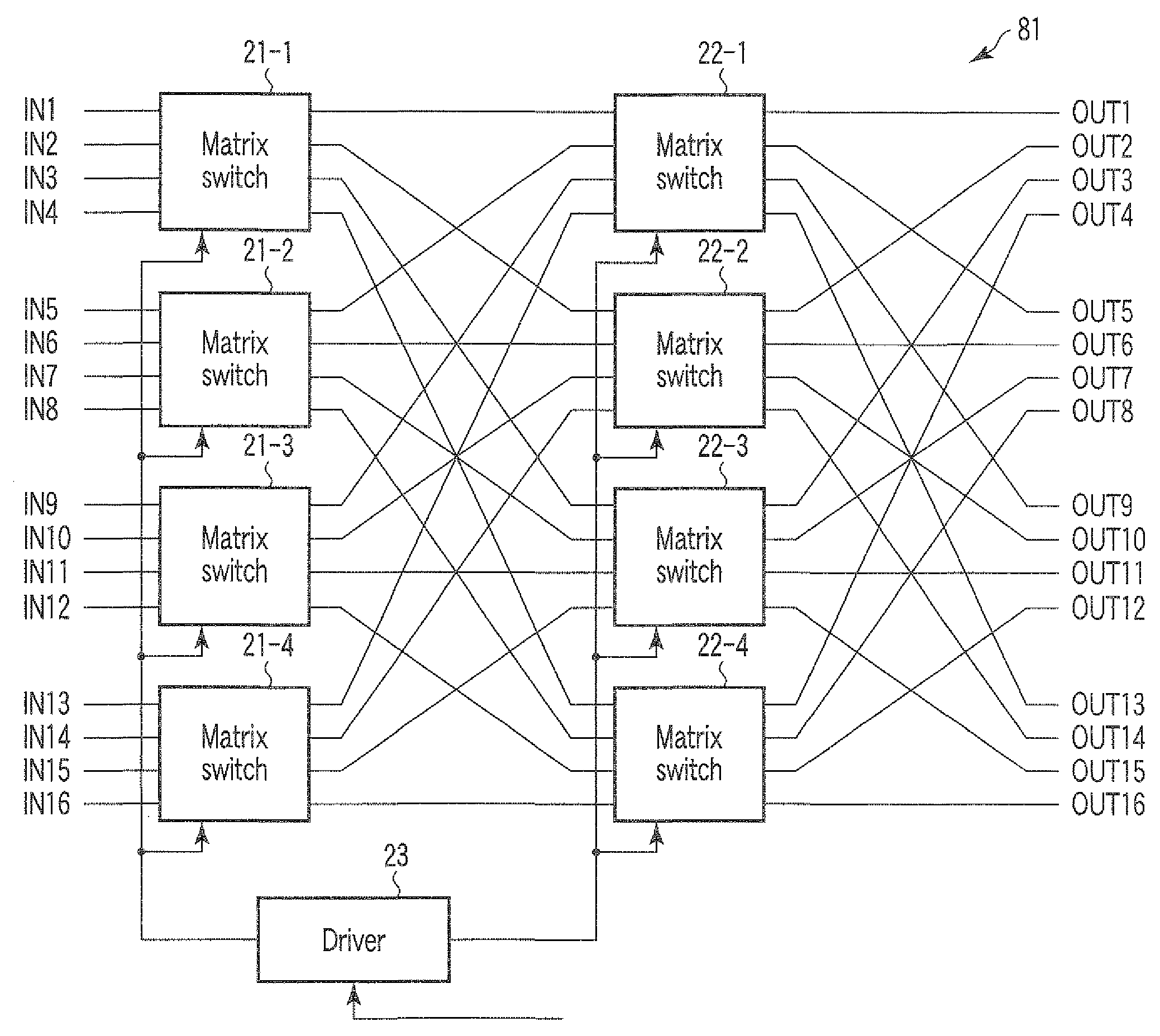
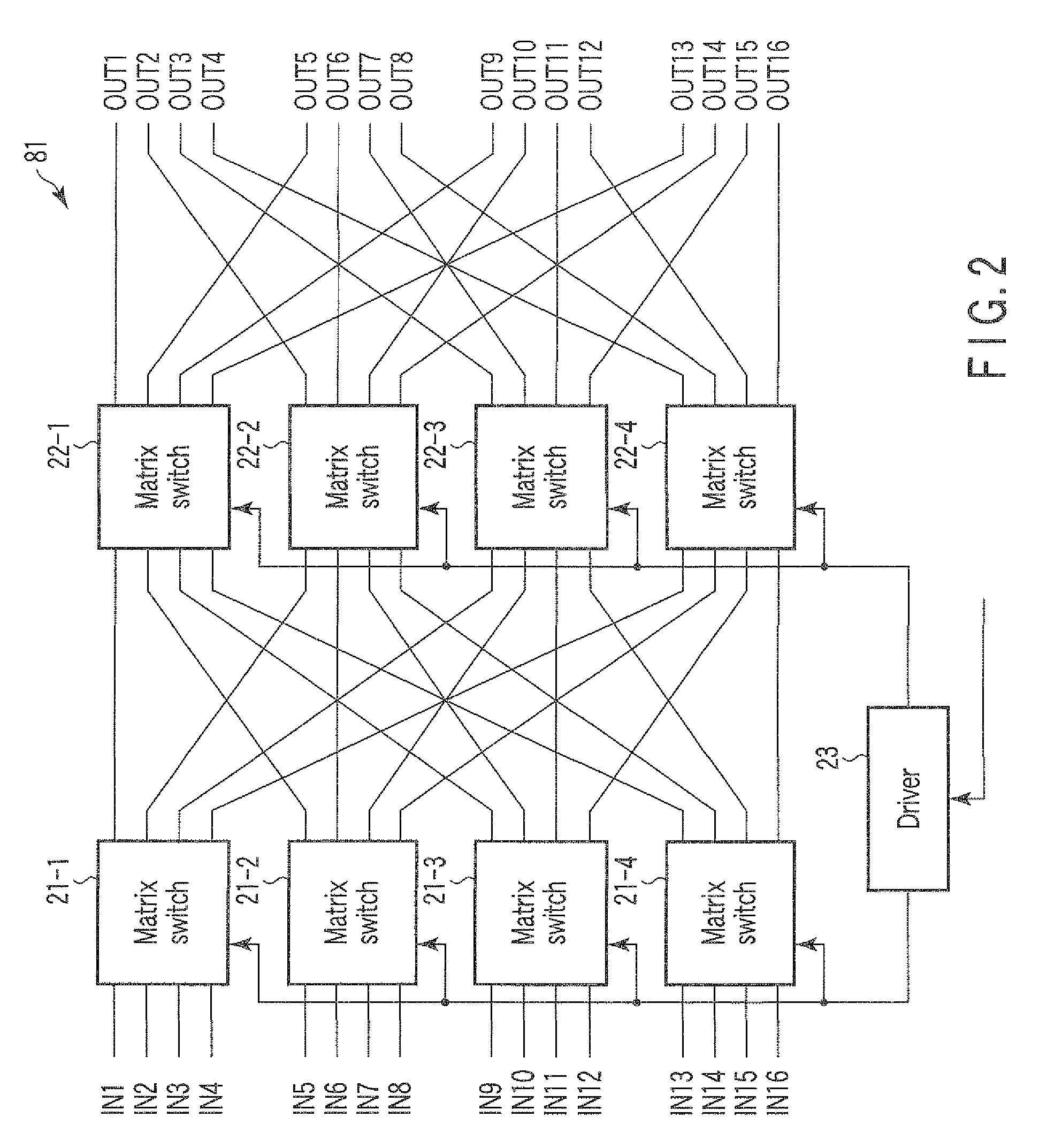
[0055]FIG. 2 is a view showing a structure of a signal selecting circuit 8a according to a first embodiment which can be utilized as a selector 8a or a selector 8b. Both a maximum number of input signals and a maximum number of output signals of this signal selecting circuit 81 are “16”.
[0056]The signal selecting circuit 81 includes matrix switches 21-1 to 21-4, matrix switches 22-1 to 22-4, and a driver 23.
[0057]All of the matrix switches 21-1 to 21-4 and the matrix switches 22-1 to 22-4 are matrix switches having a known four-input / four-output (4×4) structure.
[0058]Signals respectively output from element coils provided in the RF coil units 6c and 6d are input to a total of 16 input terminals provided to the matrix switches 21-1 to 21-4. It is to be noted that signals input to the matrix switch 21-1 are referred to as input signals IN1 to IN4, signals input to the matrix switch 21-2 are referred to as input signals IN5 to IN8, signals input to the matrix switch 21-3 are referred t...
second embodiment
[0114]FIG. 10 is a view showing a structure of a signal selecting circuit 82 according to a second embodiment which can be utilized as a selector 8a or a selector 8b. Both a maximum number of input signals and a maximum number of output signals of this signal selecting circuit 82 are “32”.
[0115]The signal selecting circuit 82 includes matrix switches 24-1 to 24-4, matrix switches 25-1 to 25-4, and a driver 26.
[0116]Each of the matrix switches 24-1 to 24-1 and the matrix switches 25-1 to 25-4 is a matrix switch having a known 8×8 structure.
[0117]Signals output from respective element coils provided in the RE coil units 6c and 6d are input to a total of 32 input terminals provided to the matrix switches 24-1 to 24-4. It is to be noted that signals input to the matrix switch 24-1 are referred to as input signals IN1 to IN8, signals input to the matrix switch 24-1 are referred to as IN9 to IN16, signals input to the matrix switch 24-3 are referred to as IN17 to IN24, and signals input t...
third embodiment
[0121]FIG. 11 is a view showing a structure of a signal selecting circuit 83 according to a third embodiment which can be utilized as a selector 8a or a selector 8b. Both a maximum number of input signals and a maximum number of output signals of this signal selecting circuit 83 are “64”.
[0122]The signal selecting circuit 83 includes matrix switches 27-1 to 27-8, matrix switches 28-1 to 28-8, and a driver 29.
[0123]Each of the matrix switches 27-1 to 27-8 and the matrix switches 28-1 to 28-B is a matrix switch having a known 8×8 structure.
[0124]Signals IN1 to IN64 output from element coils provided to RF coil units 6c and 6d are input to a total of 64 input terminals provided to the matrix switches 27-1 to 27-8, respectively.
[0125]Eight output terminals of each of the matrix switches 27-1 to 27-8 are connected with input terminals provided to each of the matrix switches 28-1 to 28-8, respectively. Signals output from first output terminals provided to the matrix switches 28-1 to 28-8...
PUM
 Abstract
Description
Claims
Application Information
 - R&D Engineer
- R&D Manager
- IP Professional
- Industry Leading Data Capabilities
- Powerful AI technology
- Patent DNA Extraction
Browse by: Latest US Patents, China's latest patents, Technical Efficacy Thesaurus, Application Domain, Technology Topic.
© 2024 PatSnap. All rights reserved.Legal|Privacy policy|Modern Slavery Act Transparency Statement|Sitemap