Rack mounted component door system and method

a component door and component technology, applied in the field of rack mounted components, can solve the problems of difficult access to the features of components that cannot be accessed from the front side of the rack, and achieve the effect of improving the service life of components and avoiding the need for maintenan

Inactive Publication Date: 2009-05-26
LEVITON MFG
View PDF23 Cites 29 Cited by
  • Summary
  • Abstract
  • Description
  • Claims
  • Application Information

AI Technical Summary

Problems solved by technology

Unfortunately, the components can have features that cannot be accessed from the front side of the rack.
These features may be accessed from the backside of the racks, which is troublesome unless the backside of the racks are easily accessible.
However, if the racks are positioned so that their backsides are against a wall or against a backside of another rack, access to these components features can be problematic.

Method used


Image

  • Rack mounted component door system and method
  • Rack mounted component door system and method
  • Rack mounted component door system and method

Examples


Embodiment Construction

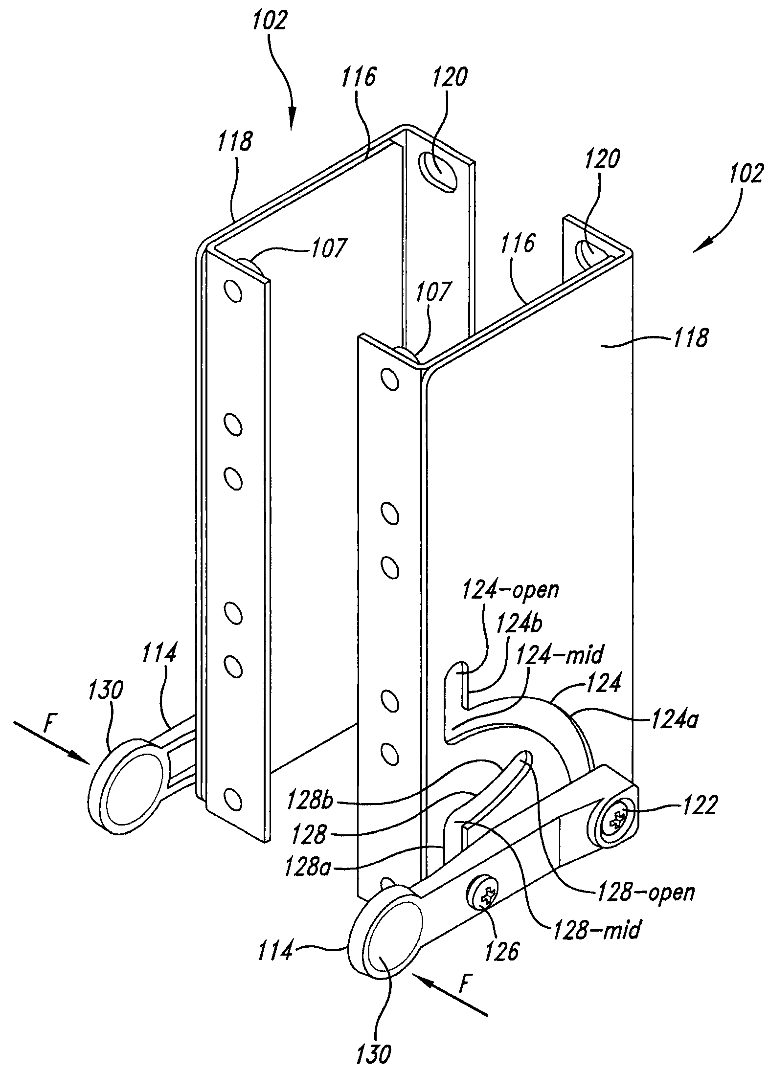
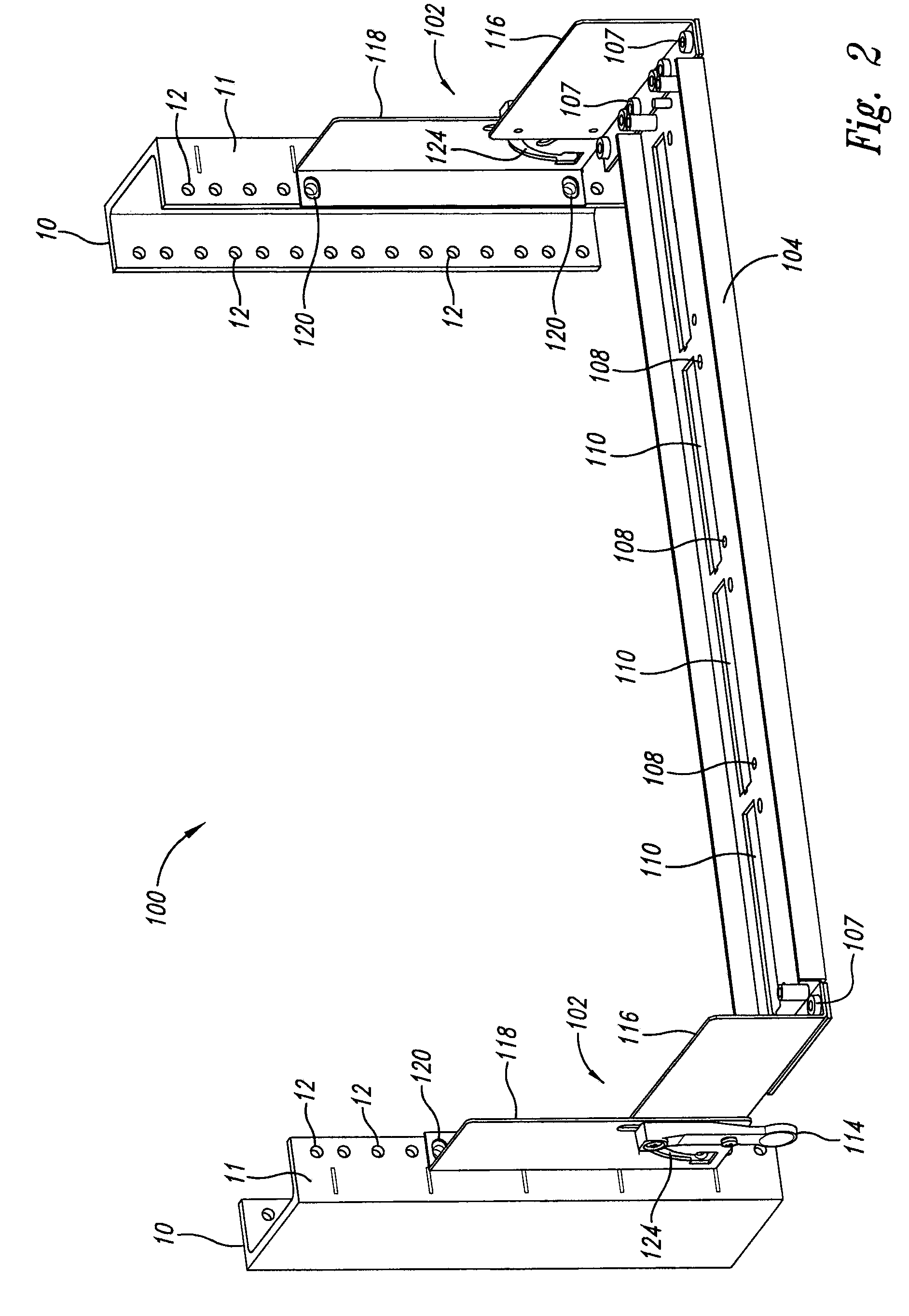
[0019]A component door system according to the present invention is used in conjunction with a conventional component rack to secure components in the rack and to provide access to features of the components positioned away from the front side of the rack. The component door system includes two hinge assemblies that can be attached directly to two opposing vertical members of the front side of a conventional rack. The component door system includes a panel that can be of conventional configuration or tailored for the component door system. The panel is attached to the two hinge assemblies to extend between the two front side vertical members of the rack.

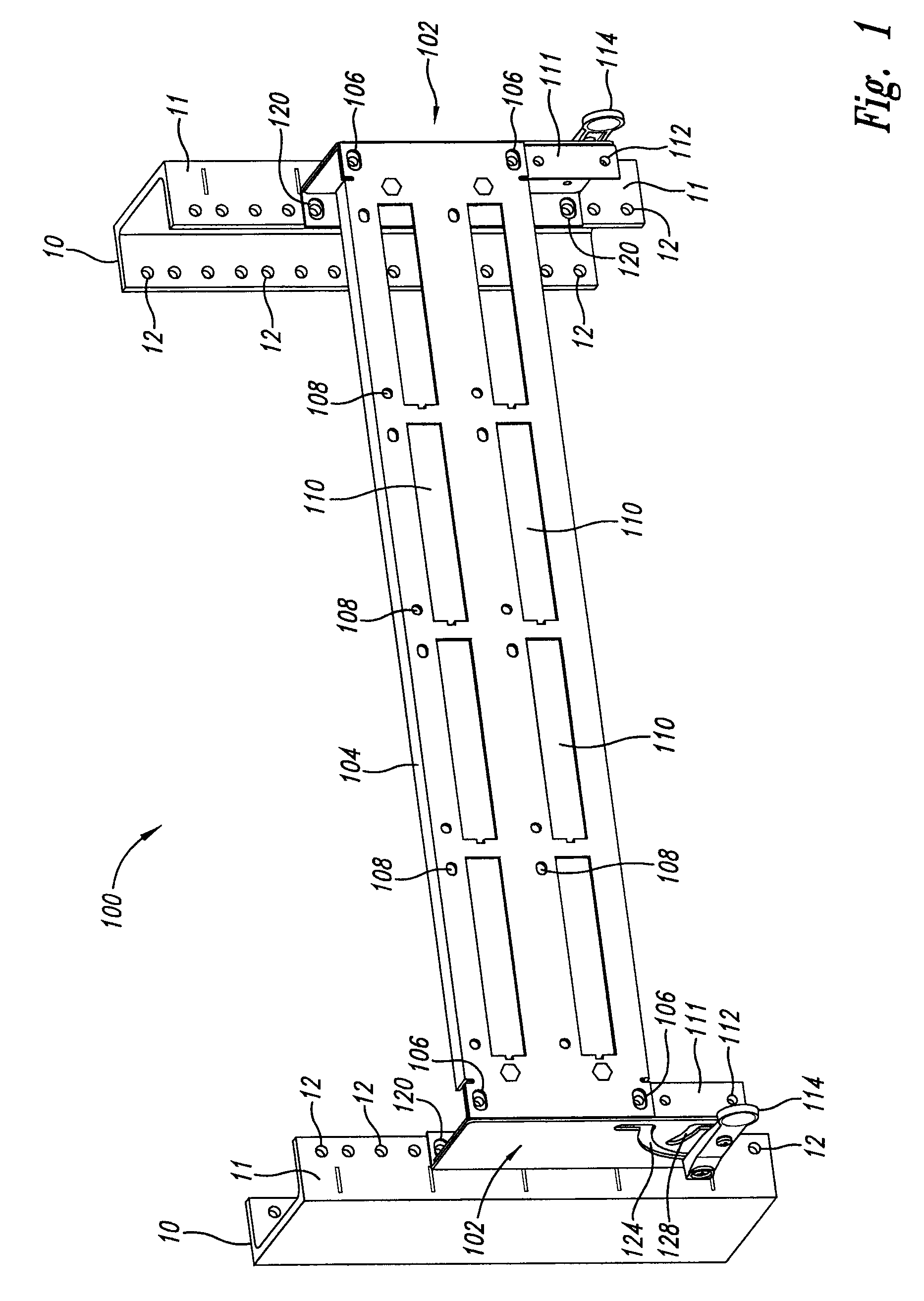
[0020]Opposing conventional vertical racks members 10 having a front side 11 with bolt holes for receiving attachment of conventional components (not shown) and associated panels (not shown) are shown in FIG. 1 as having an implementation of a component door system 100 according to the present invention attached thereto.

[0021]The com...


PUM


Abstract

A rack mounted component door system according to the present invention is used in conjunction with a conventional equipment rack to secure components in the rack and to provide access to features of the components positioned away from the front side of the rack. The component door system includes two hinge assemblies that can be attached directly to two opposing vertical members of the front side of a conventional rack. The component door system also includes a panel that can be of conventional configuration or tailored for the component door system. The panel is attached to the two hinge assemblies to extend between the two front side vertical members of the rack.

Description

CROSS REFERENCE TO RELATED APPLICATION[0001]This application claims priority benefit of provisional application Ser. No. 60 / 646,322 filed Jan. 21, 2005.BACKGROUND OF THE INVENTION[0002]1. Field of the Invention[0003]The present invention relates generally to the field of equipment racks, and more particularly to the field of component support provided by such racks.[0004]2. Description of the Related Art[0005]Racks, frames, cabinets and the like (referred to generally herein as “racks”) support computer and other electronic equipment and doors and panels (referred to generally herein as “components”). The racks and the components are mutually sized to accommodate placement of the components within the racks. Racks can include vertical members generally spaced a selected standardized distance from one another and cross-members extending between the vertical members. Both the vertical members and the cross-members can have attachment points where the components are secured. These atta...

Claims


Application Information

Patent Timeline
Patent Type & Authority Patents(United States)
IPC IPC(8): E05D11/06
CPCH04Q1/09E05D3/18E05D15/40H04Q2201/02H04Q2201/08Y10T16/5443E05Y2900/132Y10T16/5444Y10T16/379Y10T16/5445
Inventor LAURSEN, ERIK
Owner LEVITON MFG
Why Eureka
Try Eureka