Transfer pump

a technology of transfer pump and pump body, which is applied in the direction of positive displacement liquid engine, piston pump, liquid fuel engine, etc., can solve the problems of heat buildup within the pump volute and chamber, water is often somewhat dirty, and the priming centrifugal pump in general does not provide prolonged wetting, cooling and lubrication

Active Publication Date: 2009-05-26
LIBERTY PUMPS
View PDF13 Cites 18 Cited by
  • Summary
  • Abstract
  • Description
  • Claims
  • Application Information

AI Technical Summary

Problems solved by technology

Such water is often somewhat dirty and may contain pieces of solid material such as grit, scale, small wood scraps, or construction debris.
During the period of time when “self priming,” i.e. internal recirculation is occurring, there is a risk that heat buildup may occur within the pump volute and chamber.
Current self-priming centrifugal pumps in general do not provide prolonged wetting, cooling, and lubrication of the pump shaft seal, and failure thereof during a prolonged period of self priming is a problem.
Portable transfer pumps are also often exposed to a variety of adverse environmental conditions, such as heat, cold, and rain or snow.
Such pumps are further subjected to generally rough handling, being repeatedly moved from job site to job site, often unprotected and exposed to the elements.
However such pump comprises a rather complex multi-piece casing, volute, and cover assembly and combination of fasteners that is quite likely expensive to manufacture.

Method used


Image

  • Transfer pump
  • Transfer pump
  • Transfer pump

Examples


Embodiment Construction

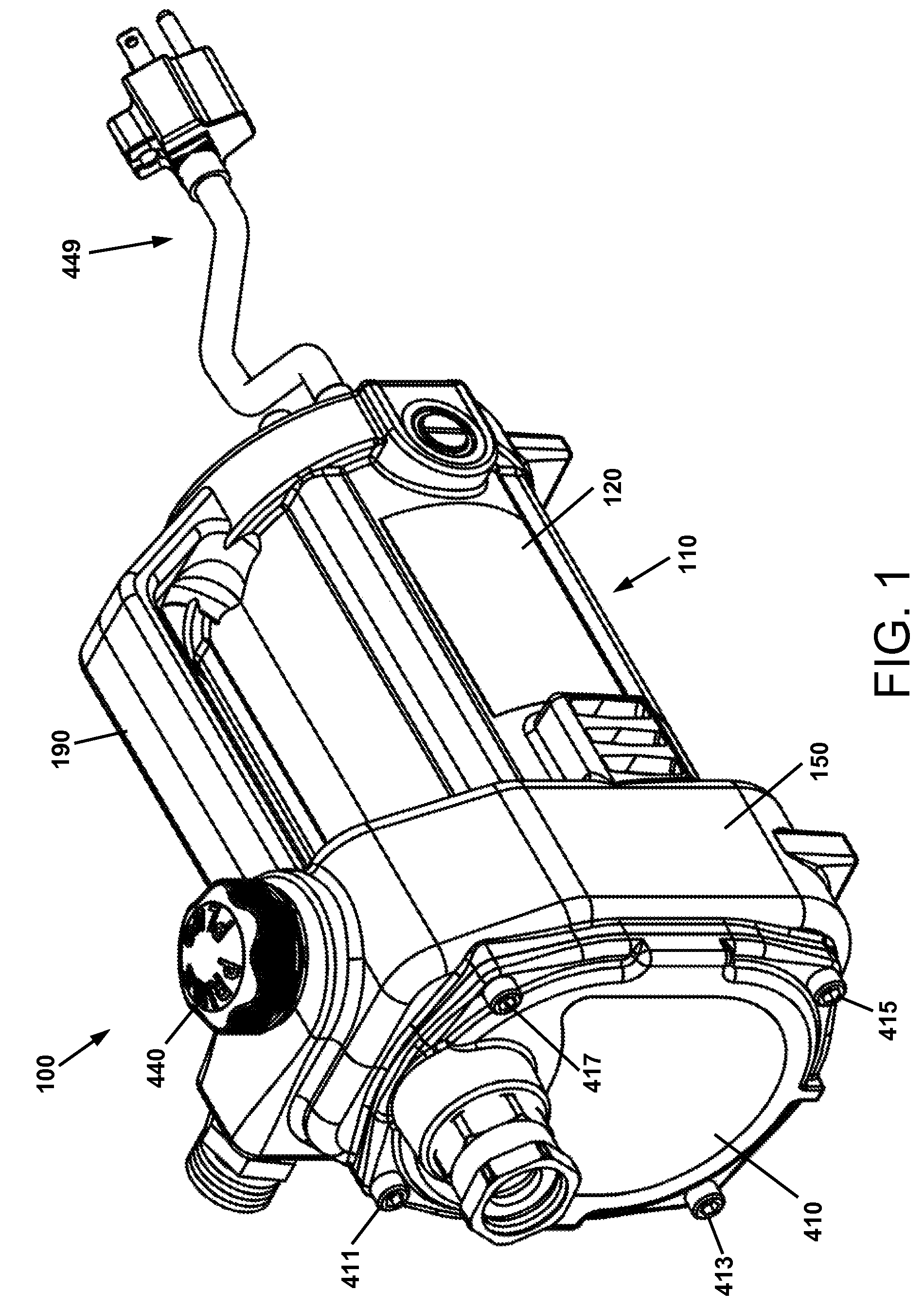
[0053]For a general understanding of the present invention, reference is made to the drawings. In the drawings, like reference numerals have been used throughout to designate identical elements.

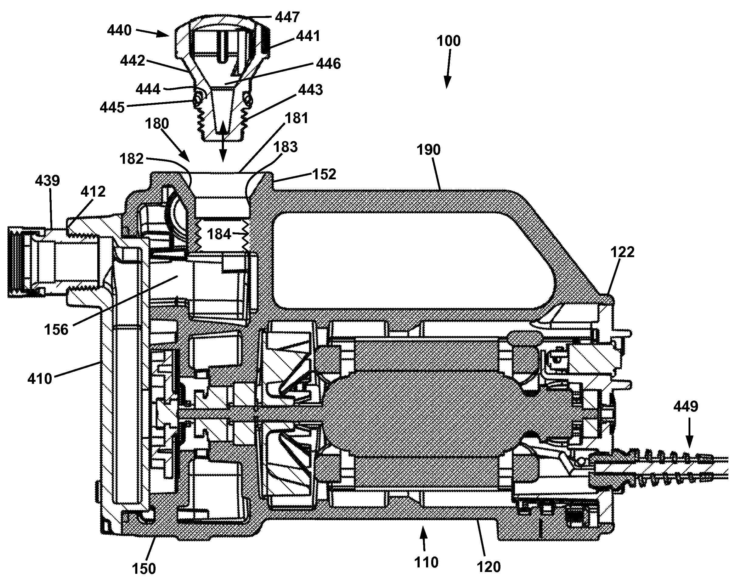
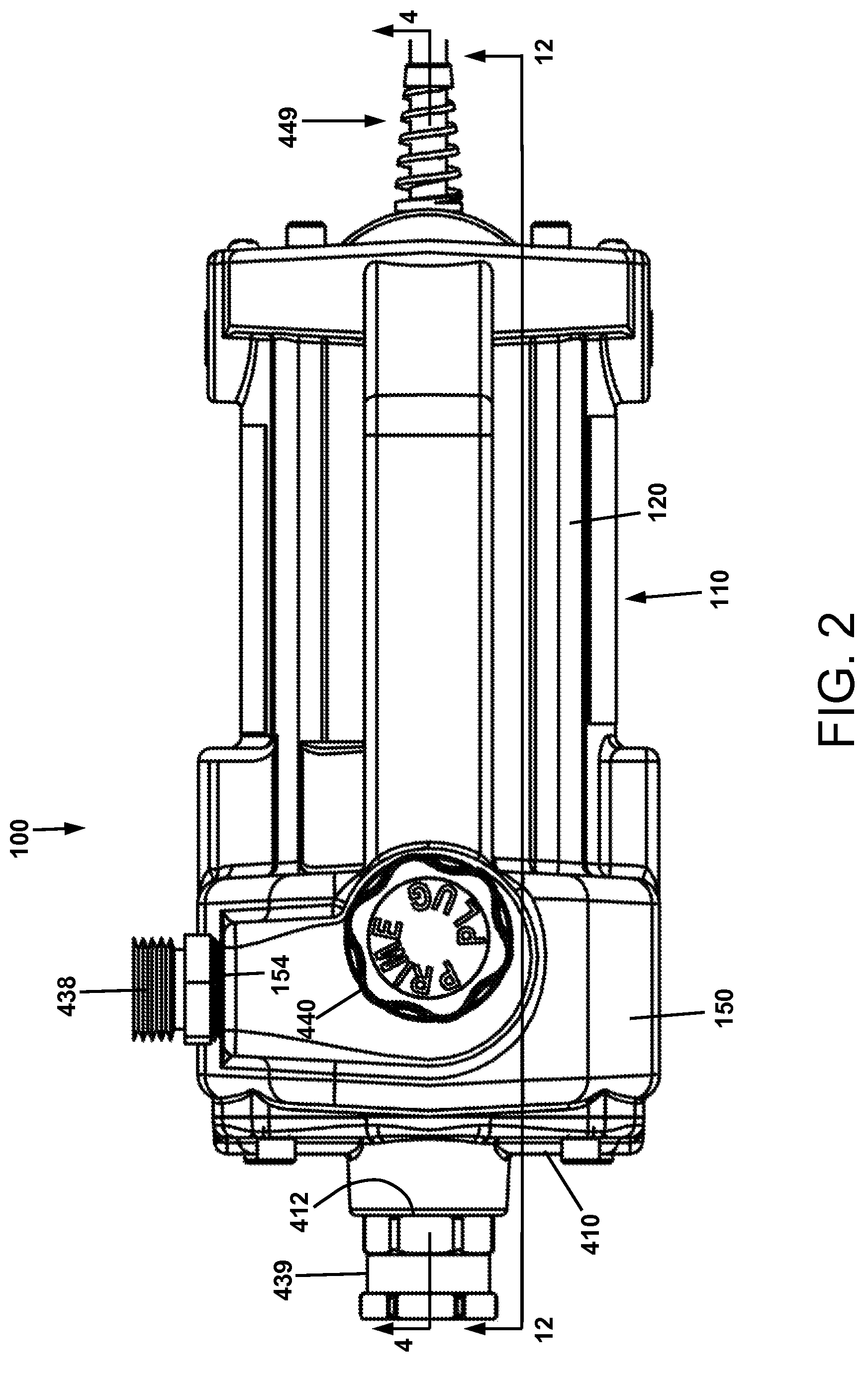
[0054]FIG. 1 is a perspective view of one embodiment of the transfer pump of the present invention. Referring to FIGS. 1 through 4, transfer pump 100 comprises a one piece i.e. unitary housing 110, a cover 410, a filler cap 440, and an electrical cord assembly 449. Housing 110 comprises a first portion 120 that is generally cylindrical and that houses a motor, a second casing portion 150 within which is formed a pump cavity, and a handle 190 that extends from an upper edge 122 of the first portion 120 to an upper edge 152 of the second portion 150 of the housing 110.

[0055]In operation of pump 100, fluid is taken in through inlet 412 in cover 410, and is discharged through outlet port 154 in pump casing 150. For the convenience of users, pump 100 is preferably provided with inlet fitting 439 a...


PUM


Abstract

A portable self-priming transfer pump comprising a one piece unitary housing, comprised of a first portion that houses a motor, a second casing portion within which is formed a pump cavity, and a handle; and a one piece cover fitted to the outboard end of the second portion of the housing.

Description

[0001]This invention relates in one embodiment to a liquid pump, and more particularly to a general liquid transfer pump having self-priming and seal self-lubricating capabilities.FIELD OF THE INVENTION[0002]Portable liquid pumps for transfer of water or other liquids in temporary circumstances.BACKGROUND OF THE INVENTION[0003]Centrifugal pumps are widely used in a variety of fluid transport applications. A rotating impeller is driven by an internal or external power source, drawing liquid into a pump chamber, and expelling liquid therefrom at increased pressure. In the most typical configuration, liquid flows into an axial inlet of the impeller, is forced by the impeller through a toroidal flow path formed by a volute surrounding the impeller, and is discharged from the volute and out of the pump.[0004]Access to the interior of the volute and the impeller is occasionally needed, for inspection, repair, or to clear out debris trapped between the volute and impeller. The latter insta...

Claims


Application Information

Patent Timeline
Patent Type & Authority Patents(United States)
IPC IPC(8): F04B35/04F01D25/16H02K9/06F04B17/00F04B23/08F04D13/06F04D29/42
CPCF04B23/08F04D13/06F04D29/426F04D29/5806
Inventor POHLER, DONALD M.
Owner LIBERTY PUMPS
Why Eureka
Try Eureka