
Method and apparatus for parameter estimation in a generalized rake receiver

a generalized rake receiver and parameter estimation technology, applied in the field of wireless communication services, can solve the problems of impairment correlations with sufficient accuracy and rapidity, and the performance of a conventional rake receiver is degraded

Active Publication Date: 2009-05-26
TELEFON AB LM ERICSSON (PUBL)
View PDF32 Cites 10 Cited by
  • Summary
  • Abstract
  • Description
  • Claims
  • Application Information

AI Technical Summary

Benefits of technology

[0009]Of course, the present invention includes additional features and advantages as highlighted in the following detailed discussion. Those skilled in the art will recognize additional features and advantages upon reading that discussion, and upon viewing the accompanying drawings.
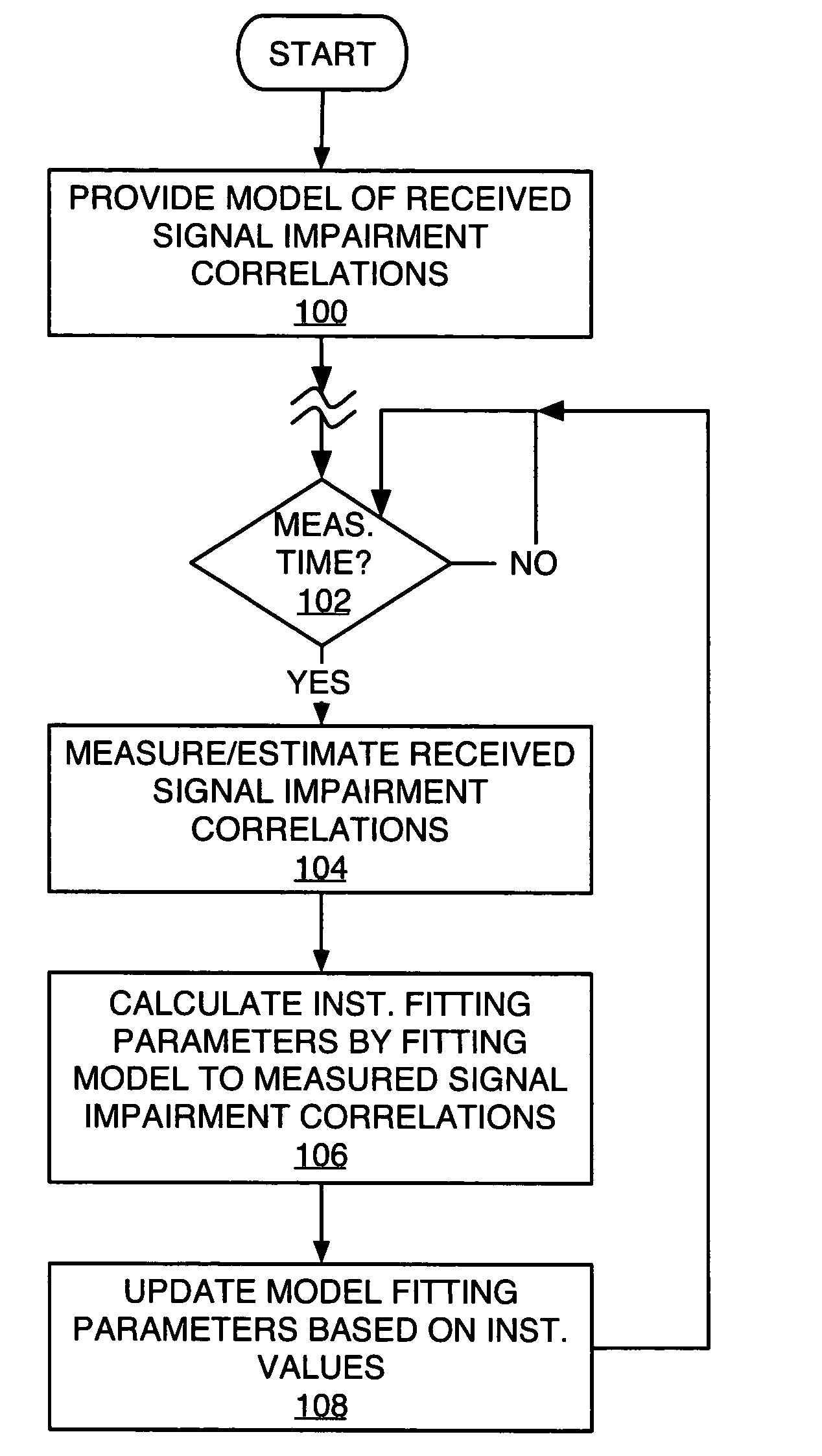
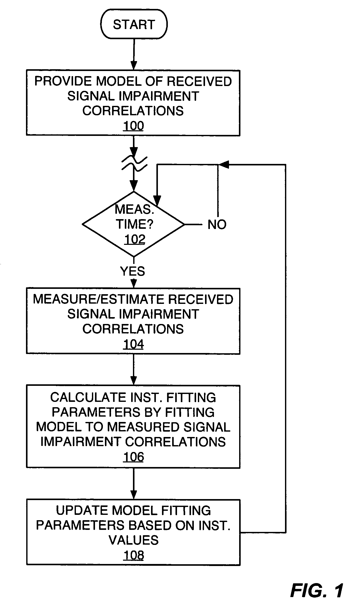
[0010]FIG. 1 is a diagram of an exemplary method of modeling received signal impairment correlations according to the present invention.
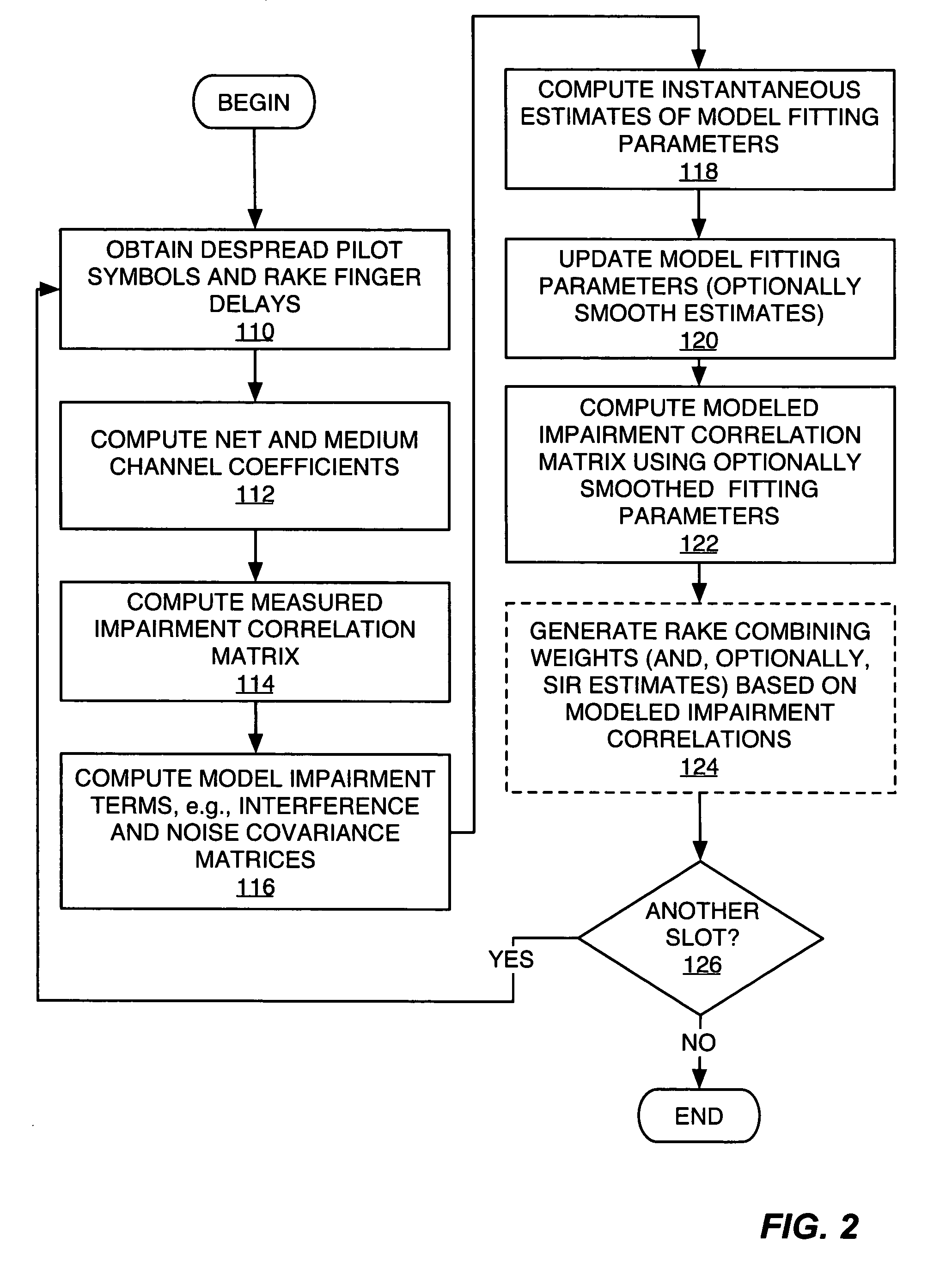
[0011]FIG. 2 is a more detailed diagram of an exemplary method of modeling received signal impairment correlations according to the present invention.
[0012]FIG. 3 is another exemplary embodiment of modeling received signal impairment correlations.
[0013]FIG. 4 is a diagram of a simplified transmitter and receiver, wherein the receiver includes a generalized RAKE receiver circuit according to one or more embodiments of the present invention.
[0014]FIG. 5 is a diagram of the generalized RAKE receiver circuit of FIG. 4.
[0015]FIG. 6 is a diagram of an exemplary combining weight and SIR generator included in the circuit of FIG. 5.
[0016]FIG. 7 is a diagram of an exemplary wireless communication network, in which a mobile terminal includes a receiver circuit configured according to the present invention.
[0017]In accordance with one or more exemplary embodiments of the present invention, a receiver, such as the receiver circuit of a mobile terminal for use in a wireless communication network, includes a generalized RAKE receiver circuit that generates RAKE combining weights and SIR estimates based on modeled received signal impairment correlations. As is known in the RAKE receiver arts, the output signals obtained from the individual RAKE fingers can include cross-correlated “impairments.” As used herein, the term “impairment” has a broad definition that includes, but is not limited to, one or more of the following items: self and multi-user interference and noise. For additional background regarding exemplary generalized RAKE operations, one may refer to the co-pending and commonly assigned U.S. patent application assigned Ser. No. 09 / 344,899, which is incorporated herein by reference.
[0018]In the generalized RAKE architecture, denoted as “G-RAKE” herein, the combining weights used to combine the RAKE finger outputs are compensated for cross-finger correlations in one or more of these impairment terms, and the present invention provides a method and apparatus for carrying out such compensation using a model-based approach. FIG. 1 broadly outlines an exemplary method to implement the present invention's model-based method of impairment correlation estimations. In the context of FIG. 1, the exemplary model comprises one or more impairment terms, which may comprise structured elements, e.g., particularly defined matrices, with each term being scaled by a model fitting parameter. This model structure is explored in much greater detail later herein.
[0019]In examining the illustrated processing logic, one sees that processing “begins” with providing a model of received signal impairment correlations (Step 100). Those skilled in the art will appreciate that “providing” in this context may comprise configuring a Digital Signal Processor (DSP), microprocessor, or other processing logic, to implement an impairment correlation model according to stored computer instructions. With the model available, the exemplary receiver estimates impairment correlations from received signal measurements at successive instants in time, and then updates the model based on these measurements. In this sense, then, the present invention provides an adaptive modeling method that “learns” impairment correlations directly from received signal measurements.
[0020]Thus, if it is time to make such measurements and update the model (Step 102), the exemplary receiver logic measures received signal impairment correlations—at least for the impairment terms of interest—(Step 104), and calculates instantaneous values for the model's fitting parameters (Step 106). These instantaneous values are then used to update the model's fitting parameters, such that the model of received signal impairment correlations tracks changing reception conditions (Step 108).
[0021]Turning to exemplary model details, the impairment correlation matrix R of a received signal for a mobile terminal receiving CDMA signal transmissions from a radio base station can be expressed as a function of certain parameters based on the theoretical expression given as,
where Ep is the pilot energy per unit time, Et is the total base station energy per unit time, N is the spreading factor, C is a scaling factor, N0 is the noise factor, RI is an interference correlation matrix, and Rn is a thermal noise correlation matrix arising from the autocorrelation properties of receiver filtering. Note that RI may be constructed as an interference covariance matrix and Rn may be constructed as a noise correlation matrix. The terms “covariance” and “correlation” as used herein should be understood as interchangeable unless the context of a particular passage makes an explicit distinction between the two terms. Those skilled in the art will, of course, appreciate that covariance is a special case of cross-correlation with zero mean.
[0023]In looking at Eq. (1) above, it should be noted that a receiver generally cannot know Et / Ep and N0 explicitly. One or more exemplary embodiments of the present invention obviates this problem by determining the model's impairment terms (RI and Rn) explicitly using channel coefficient and receiver pulse shape information. Those skilled in the art will appreciate that a given receiver can be configured with knowledge of its receiver filter pulse shape, e.g., its filter autocorrelation function, and can maintain channel coefficient estimates based on receiving pilot symbols, training data, or other signal known a priori to the receiver such that reception of the known signal can be used to characterize the propagation channels. Exemplary formulas are given herein for computing RI and Rn in terms of channel coefficient and pulse shape information. Thus, the present invention provides an impairment correlation model that, in an exemplary embodiment, comprises an interference term that is scaled by a first model fitting parameter, and a noise term that is scaled by a second model fitting parameter. Using this method, the impairment correlations, R, can be modeled as,

Problems solved by technology

However, as is known to those skilled in the art, the conventional RAKE receiver is optimal only in certain limited circumstances.
For example, the presence of self-interference and multi-user access interference both degrade the performance of a conventional RAKE receiver.
Of course, the need to determine signal impairment correlations with sufficient accuracy and rapidity stands as a primary challenge associated with implementation of the generalized RAKE receiver.

Method used


Image

  • Method and apparatus for parameter estimation in a generalized rake receiver
  • Method and apparatus for parameter estimation in a generalized rake receiver
  • Method and apparatus for parameter estimation in a generalized rake receiver

Examples


second embodiment

[0054]While specific approaches for channel estimation and parameter fitting are given, the invention is not limited to these particular approaches. Below is described a second embodiment which employs different approaches for channel estimation and parameter fitting. This embodiment offers an exemplary method of computing channel estimates based on an interpolative approach. The summation limits in the below equations assume a WCDMA slot wherein one transmit antenna sends ten pilot symbols per traffic slot.

[0055]With the second embodiment, the medium coefficients are set equal to the net coefficients (ĝ={tilde over (h)}). The net coefficients are computed for all fingers as an interpolative function of time within the slot. Specifically, Step 112 computes the net and medium coefficients using

[0056]h~⁡(m)=(7-m5)⁢15⁢∑i=04⁢x⁡(i)⁢s*⁡(i)+(m-25)⁢15⁢∑i=59⁢x⁡(i)⁢s*⁡(i)(19)

The two summation terms may be viewed as channel measurements. With this time varying response, the measured impairment...

first embodiment

[0070]For a mobile terminal not using HS-DSCH service, several options are available. One is to simply use the present invention as exemplified by the processing logic of FIG. 2. The model fitting parameter values can be averaged over the two states of base station operation. Another option is for such mobile terminals to monitor HS-DSCH control information, and use the state information to have state-dependent model fitting parameters according to the logic of FIG. 3, for example. Yet another option is for the mobile terminal blindly to estimate which state the base station is in and maintain multiple model fitting parameter values accordingly. The state can be estimated blindly by measuring impairment power and thresholding this to form different states, for example.

[0071]With the above exemplary embodiments in mind, FIG. 4 broadly illustrates a transmitter 10, e.g., a wireless network base station, and a receiver 12, e.g., a mobile terminal or other wireless communication device....


PUM


Abstract

Exemplary received signal processing may be based on maintaining a model of received signal impairment correlations, wherein each term of the model is updated periodically or as needed based on measuring impairments for a received signal of interest. An exemplary model comprises an interference impairment term scaled by a first model fitting parameter, and a noise impairment term scaled by a second model fitting parameters. The model terms may be maintained based on current channel estimates and delay information and may be fitted to measured impairment by adapting the model fitting parameters based on the measured impairment. The modeled received signal impairment correlations may be used to compute RAKE combining weights for received signal processing, or to compute Signal-to-Interference (SIR) estimates. Combined or separate models may be used for multiple received signals. As such, the exemplary modeling is extended to soft handoff, multiple antennas, and other diversity situations.

Description

BACKGROUND OF THE INVENTION[0001]The present invention generally relates to wireless communication services, and particularly relates to tracking signal impairment correlations of received communication signals.[0002]RAKE receivers are well known in the communication arts and find widespread use in Code Division Multiple Access (CDMA) systems, such as in IS-95, IS-2000 (cdma2000), and Wideband CDMA (WCDMA) wireless communication networks. The name derives from the rake-like appearance of such receivers, wherein multiple, parallel receiver fingers are used to receive multiple signal images in a received multipath signal. By coherently combining the finger outputs in a RAKE combiner, the conventional RAKE receiver can use multipath reception to improve the Signal-to-Noise Ratio (SNR) of the received multipath signal.[0003]However, as is known to those skilled in the art, the conventional RAKE receiver is optimal only in certain limited circumstances. For example, the presence of self-...

Claims


Application Information

Patent Timeline
Patent Type & Authority Patents(United States)
IPC IPC(8): H04B15/00H04B1/707
CPCH04B1/712H04B2201/709727
Inventor CAIRNS, DOUGLAS A.BOTTOMLEY, GREGORY E.WANG, YI-PIN ERICFULGHUM, TRACY L.JONSSON, ELIAS
Owner TELEFON AB LM ERICSSON (PUBL)
Learn More