Check patentability & draft patents in minutes with Patsnap Eureka AI!

Adjustable threshold fastener with flanges

a threshold fastener and adjustable technology, applied in the field of fasteners, can solve the problems of shingling and jamming of the fastener, the dimension of the fastener is different, and achieve the effect of preventing shingling and/or jamming

Active Publication Date: 2009-06-02
STAFAST PROD
View PDF86 Cites 14 Cited by
  • Summary
  • Abstract
  • Description
  • Claims
  • Application Information

AI Technical Summary

Benefits of technology

The solution effectively prevents shingling and jamming in the delivery track, ensuring smooth and reliable delivery of fasteners by limiting rotation and vertical displacement through the engagement of flanges with the track's rimmed edge, maintaining contact with the channel wall to restrain rotation.

Problems solved by technology

A particular problem in the dispensation of adjustable threshold fasteners is the fact that they tend to jam in the curvilinear track which feeds the insertion mechanism.
The weight, momentum and inertia of a plurality of fasteners apply pressure to the fasteners when they abruptly stop in the track due to a stoppage in the demand for the fasteners.
Additionally, variance in the dimensions of the fasteners is a contributing cause to the shingling and jamming of the fasteners.

Method used


Image

  • Adjustable threshold fastener with flanges
  • Adjustable threshold fastener with flanges
  • Adjustable threshold fastener with flanges

Examples


Embodiment Construction

and the Claims which follow hereinbelow.

BRIEF DESCRIPTION OF THE DRAWINGS

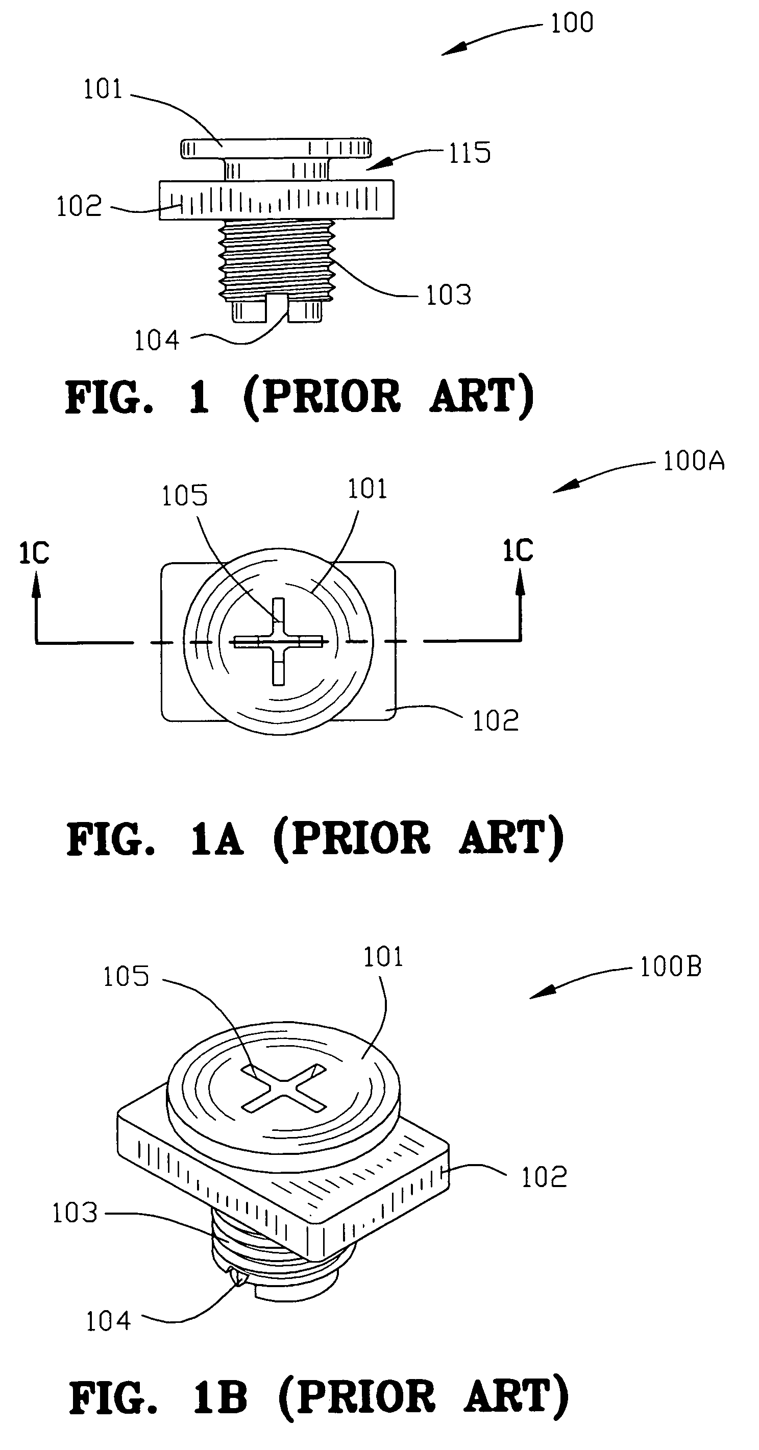
[0018]FIG. 1 is a side view of a prior art fastener.

[0019]FIG. 1A is a top view of the prior art fastener of FIG. 1.

[0020]FIG. 1B is a perspective view of the prior art fastener of FIG. 1B.

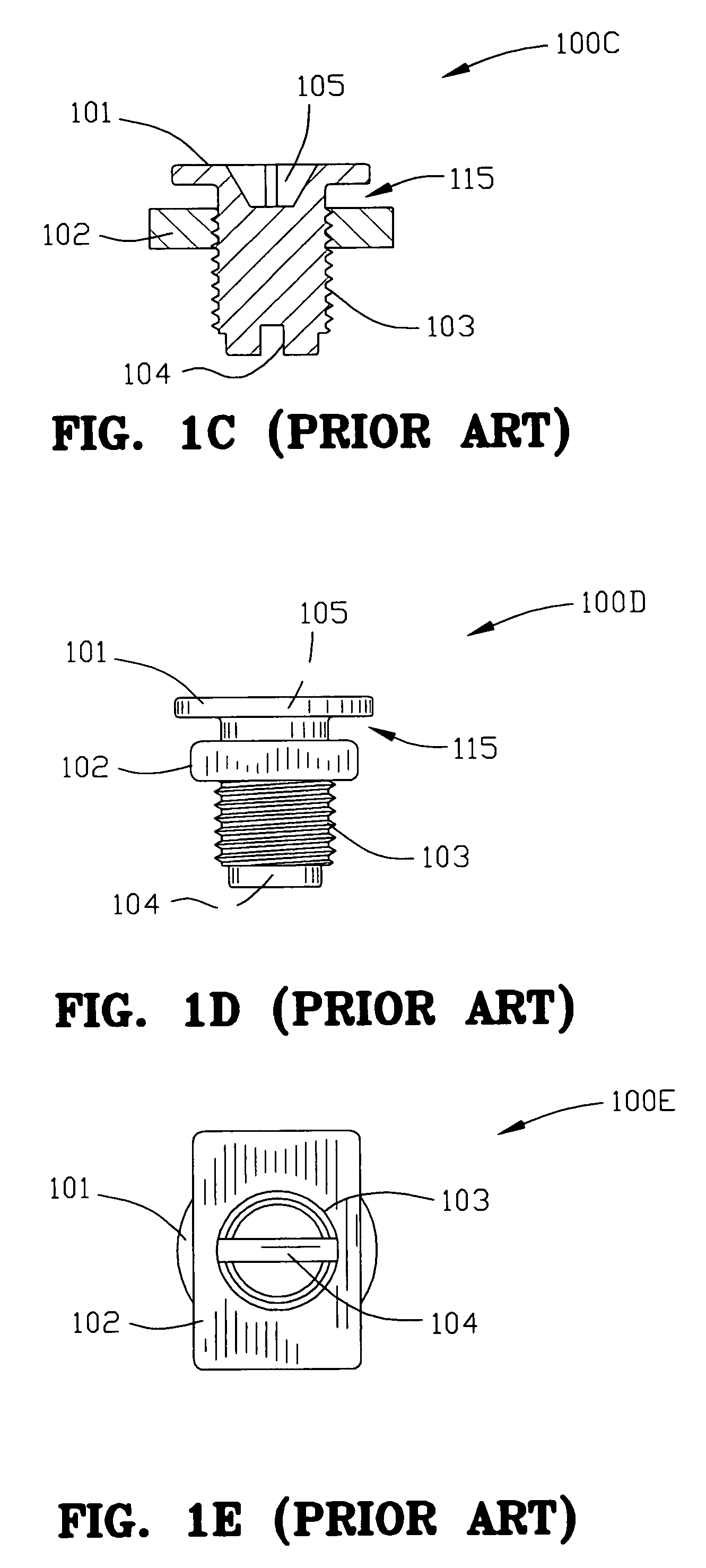
[0021]FIG. 1C is a cross-sectional view of the prior art fastener taken along lines 1C-1C of FIG. 1A.

[0022]FIG. 1D is an end view of the prior art fastener of FIG. 1.

[0023]FIG. 1E is a bottom view of the prior art fastener of FIG. 1.

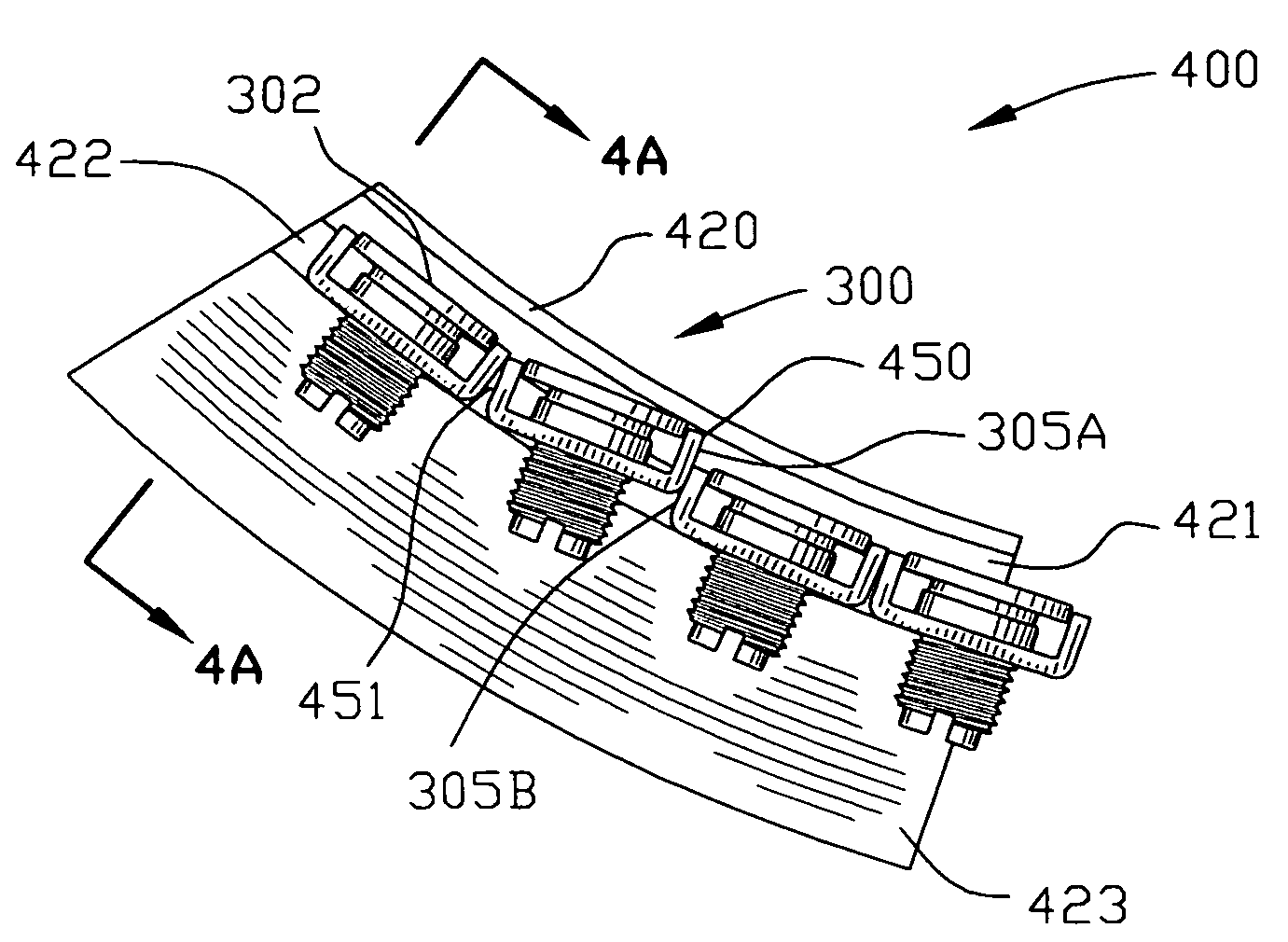
[0024]FIG. 2 is a side view of the interior of a section of a curvilinear track with several prior art fasteners located therein.

[0025]FIG. 2A is an end view of the track of FIG. 2 illustrating a prior art fastener therein.

[0026]FIG. 3 is a perspective view of the fastener of the instant invention.

[0027]FIG. 3A is a top view of the fastener of the instant invention.

[0028]FIG. 3B is a cross-sectional view of the instant invention taken along the lines 3B-3B of FIG. 3A.

[0029]FIG. 3C is a side view o...


PUM


Abstract

A fastener comprising a threaded stud and a rectangular nut having raised flanges is disclosed. Raised flanges enable passing the fasteners in a curvilinear dispensing track. The rectangular nut resides in a channel in a threshold device and is restrained against rotational movement. The threaded stud includes a flat head adjustable in a plurality of positions which, in turn, enables positioning of the threshold.

Description

FIELD OF THE INVENTION[0001]The invention is in the field of fasteners used in connection with door thresholds and in particular with the adjustment of the height of door thresholds.BACKGROUND OF THE INVENTION[0002]U.S. Pat. No. 5,611,173 to Headrick et al. discloses a threshold having a threaded pedestal 32 and support pad 33 as well as a correspondingly threaded lug 34 adapted to receive the threaded pedestal 32. See, FIGS. 2 and 6 of the '173 patent. Also see U.S. Pat. Nos. 5,588,266 and 5,426,894 to Headrick. Each of the foregoing patents discloses a lug 34 captured in a slot which cooperates with a threaded pedestal to vertically raise and lower a threshold.[0003]U.S. Pat. No. 6,345,477 to Keppler et al. discloses a series of screws 64 and nuts 66. According to the '477 specification: “Nuts 66 fit within the channel below web 68 between the adjacent sides. Nuts 66 are sufficiently large so that they are prohibited from turning and may transmit an axial load along the screw axis...

Claims


Application Information

Patent Timeline
Patent Type & Authority Patents(United States)
IPC IPC(8): F16B43/02E06B1/70F16B5/02F16B27/00F16B35/04F16B37/00F16B37/02
CPCE06B1/70F16B27/00F16B37/00F16B5/0233F16B35/045
Inventor SELLE, STEPHEN
Owner STAFAST PROD
Features
  • R&D
  • Intellectual Property
  • Life Sciences
  • Materials
  • Tech Scout
  • Unparalleled Data Quality
  • Higher Quality Content
  • 60% Fewer Hallucinations
Learn More