Pharmaceutical syringe piston

a technology of syringe and syringe, which is applied in the direction of screw threaded articles, infusion needles, other domestic articles, etc., can solve the problems of making the penetration of gases and/or germs into the contents of the syringe or carpule cylinder more difficult, and achieve the effect of facilitating the removal of the forming tool

Inactive Publication Date: 2009-06-16
WEST PHARMA SERVICES DEUT GMBH & CO KG
View PDF29 Cites 52 Cited by
  • Summary
  • Abstract
  • Description
  • Claims
  • Application Information

AI Technical Summary

Benefits of technology

[0010]Therefore, an object of the invention is to produce a piston stopper of the type mentioned at the outset, that can be simply and cost-effectively produced, that makes possible a better sealing of a syringe or carpule cylinder, and whereby an interaction between the material of the piston and the contents in the syringe or carpule cylinder is reliably prevented. There is the additional objective of providing a method and a device of the type mentioned at the outset, that makes possible a simple and cost-effective production of such a piston stopper.

Problems solved by technology

Due to this, particularly the penetration of gases and / or germs into the contents of the syringe or carpule cylinder is basically made more difficult.

Method used


Image

  • Pharmaceutical syringe piston
  • Pharmaceutical syringe piston
  • Pharmaceutical syringe piston

Examples


Embodiment Construction

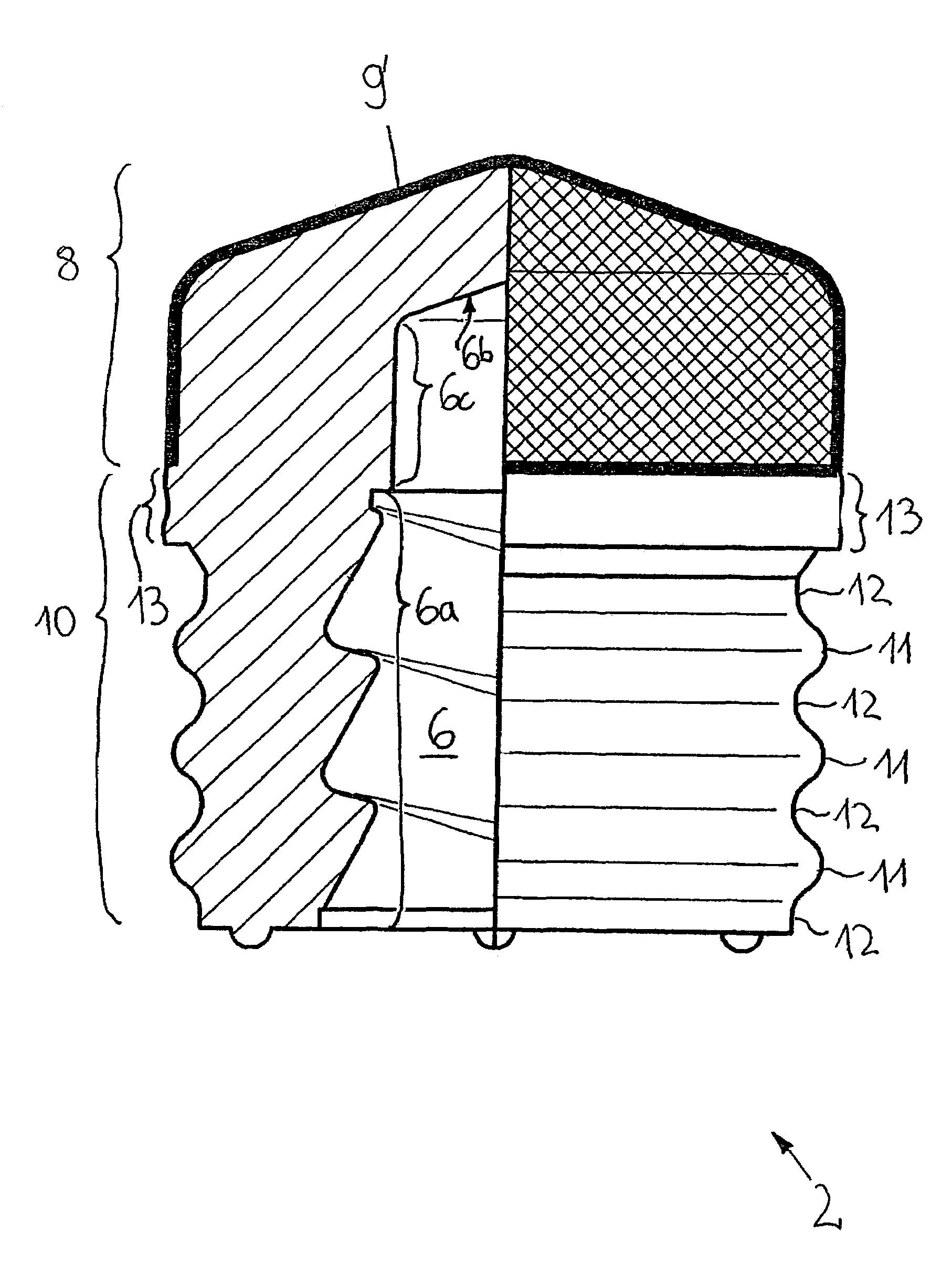
[0042]As shown in FIGS. 10 and 12, for example, a pharmaceutical syringe or carpule has a syringe or a carpule cylinder 1 with a piston stopper 2 that can be axially displaced therein. The syringe or carpule cylinder 1 has at one end a discharge orifice for a liquid pharmaceutical preparation situated in the cylindrical cavity 4 of the syringe or carpule cylinder 1, the discharge orifice being tightly closed off by a removable cover 3. The syringe or carpule cylinder 1 has a pass-through opening at that end, which is situated opposite the discharge orifice for a piston rod 5 joined with the piston stopper 2, the piston rod engaging a receiving cavity 6 of the piston stopper 2 with its end facing the receiving cavity.

[0043]As it can be particularly well seen in FIGS. 9 and 11, the piston stopper 2 has a single-piece base body 7′ made from rubber or a similar elastomer, that is enveloped in a cap-like manner by a fluorinated polymer film or a similar inert film 9′ on a cap-shaped sect...


PUM

PropertyMeasurementUnit
circumferenceaaaaaaaaaa
diameteraaaaaaaaaa
conical shapeaaaaaaaaaa

Abstract

A piston stopper (2) made substantially of rubber has a piston section (8) enclosed in cap-like manner by an inert film (9′) facing the contents of a syringe or carpule cylinder (1), the inert film (9′) being located adjacent to the syringe or carpule cylinder (1). Adjacent to the piston section (8), the piston stopper (2) has a non-coated sealing section (10). According to a device and method for producing one such piston stopper (2), a non-vulcanized rubber sheet (7) is inserted into a form tool, together with an inert film (9). Under the effect of pressure and heat, an entire piston stopper contour is formed from the layered arrangement, extending to a flange (16) which protrudes laterally beyond the piston stopper (2) in the region of the separating plane of the form tool. A receiving cavity (6) for a piston rod is created in the piston section (8). The wall area of the sealing section (10) surrounding the receiving cavity (6) is forced into the receiving cavity (6). The piston stopper (2) is subsequently separated from the flange (16) in a blanking process, whereby a peripheral sealing area (13), directly adjacent to the edge of the inert film (9′) enclosing the piston section (8), is formed in the sealing section (10).

Description

CROSS-REFERENCE TO RELATED APPLICATIONS[0001]This application is a continuation of International Application No. PCT / EP02 / 04831, filed May 2, 2002, the disclosure of which is incorporated herein by reference.BACKGROUND OF THE INVENTION[0002]The invention is directed to a method for producing a pharmaceutical piston stopper made substantially from rubber or a similar elastomer, which has a receiving cavity for connecting with a piston rod or a similar displacement transferring element and a piston section enclosed in a cap-like manner by a fluorinated polymer film or similar inert film. The piston section in the working position faces the contents of a syringe or carpule cylinder and abuts on the outer circumference with its inert film against the syringe or carpule cylinder. The piston stopper has an uncoated sealing section adjacent to this piston section which in the working position abuts against the syringe or carpule cylinder. In a forming operation a layered arrangement compri...

Claims


Application Information

Patent Timeline
Patent Type & Authority Patents(United States)
IPC IPC(8): A61M5/32A61M5/00A61M5/315B29C33/46B29C35/02B29C37/02B29C43/18B29C43/40B29C43/42B29K21/00B29K105/24B29L9/00B29L31/56
CPCA61M5/31513B29C33/46B29C37/02B29C43/184B29C43/40B29C43/42A61M5/31511Y10T29/49B29C2793/009B29K2019/00B29L2001/00B29L2031/7544B29L2031/56B29C43/18A61M2207/00A61M5/315
Inventor BRINKHUES, JURGEN
Owner WEST PHARMA SERVICES DEUT GMBH & CO KG
Why Eureka
Try Eureka