
Acoustic noise reduction device for electronic equipment, including personal computers

a technology for electronic equipment and noise reduction, which is applied in the field of acoustic noise reduction of electronic equipment, can solve the problems of annoying noise, inconvenient attachment, and annoying noise emitted from the rear of such devices, and achieve the effects of reducing acoustic noise, reducing acoustic noise emitted, and reducing the acoustic noise of air-circulating fans

Inactive Publication Date: 2009-06-23
KAWAR MAHER S
View PDF89 Cites 36 Cited by
  • Summary
  • Abstract
  • Description
  • Claims
  • Application Information

AI Technical Summary

Benefits of technology

"The patent describes an accessory device that reduces acoustic noise from a computer or other electronic equipment. It can be attached to a fan or computer without needing tools or extra pieces. The device has an acoustic barrier that allows air to flow through while absorbing noise. It can be adjusted for different sizes of devices and can be made from recyclable materials. Overall, the device helps to reduce noise and make electronic equipment more comfortable."

Problems solved by technology

Computers and other electronic equipment which utilize air circulating or cooling fans and other electronic devices generate noise.
This noise, usually emitted from the rear of such devices, can be annoying, bringing about a desire to minimize such noise.
However, such fans, when used as replacements, are inconvenient to attach, requiring tools and extra elements such as screws or bolts.
Once installed, such a fan is inconvenient to remove as this requires further time and tools.
However, such devices reduce airflow and air pressure of the fans.
In addition, such devices require tools and cannot be easily disassembled or adapted to different sizes of electronic equipment.

Method used


Image

  • Acoustic noise reduction device for electronic equipment, including personal computers
  • Acoustic noise reduction device for electronic equipment, including personal computers
  • Acoustic noise reduction device for electronic equipment, including personal computers

Examples


Embodiment Construction

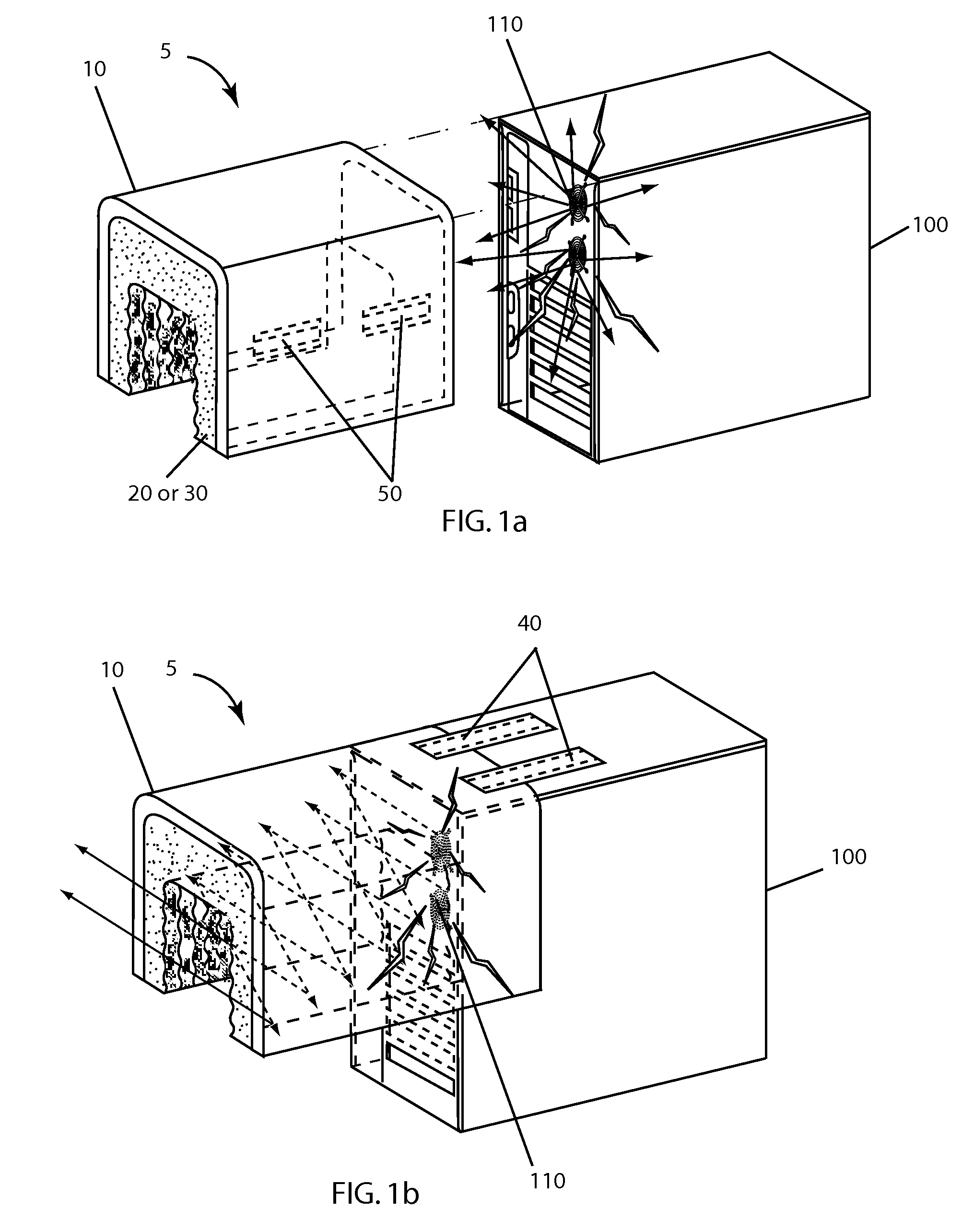
FIGS. 1a and 1b—Upside-Down U-Shaped ANR

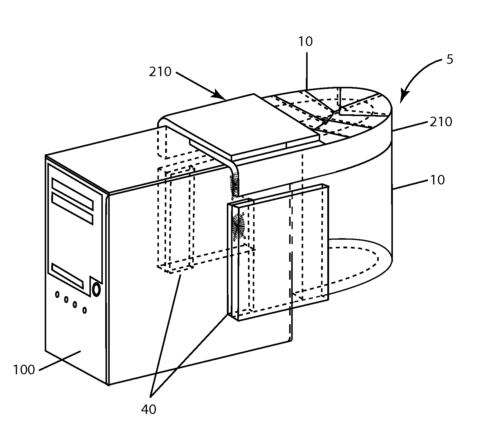
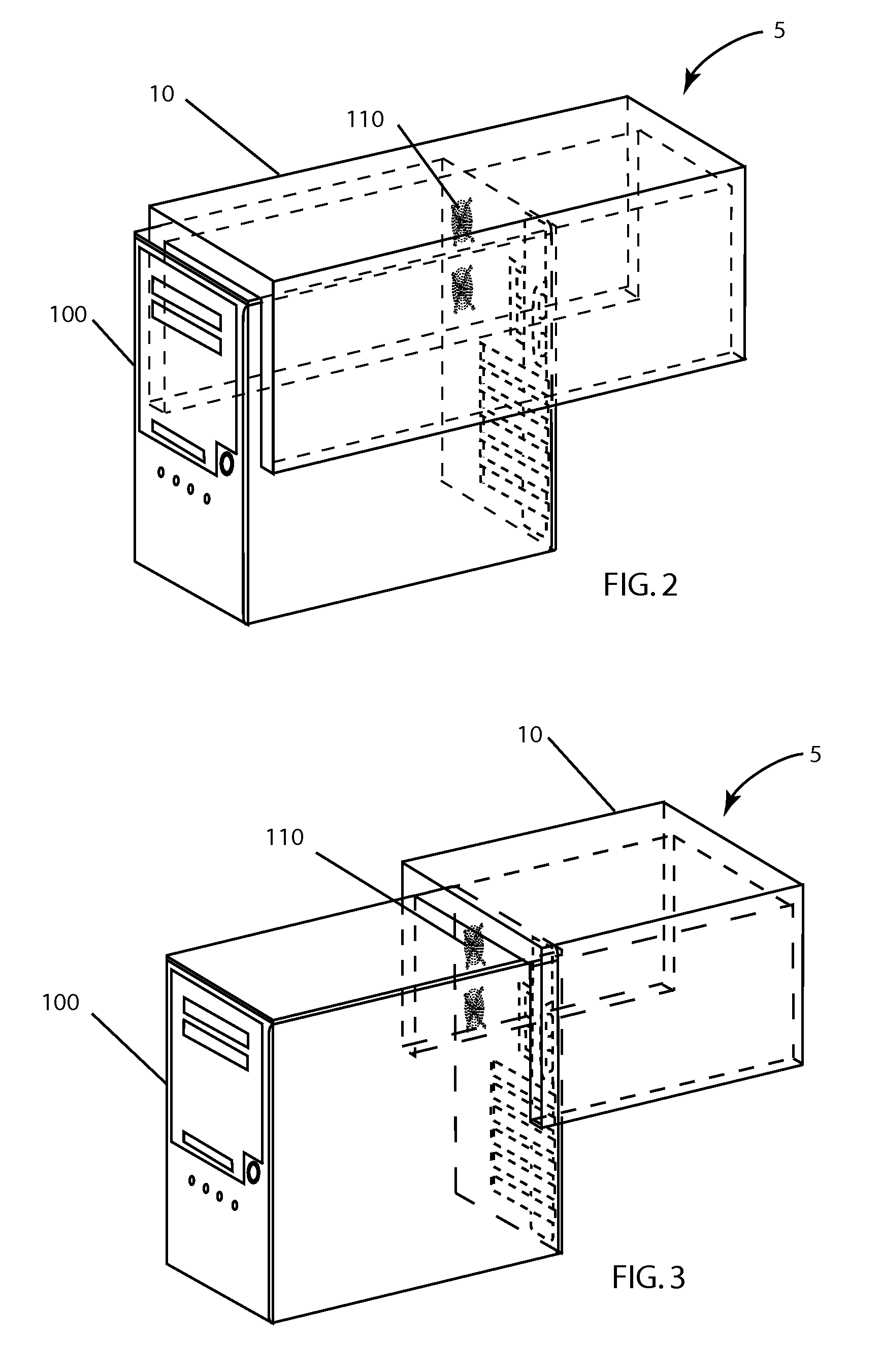
[0055]FIGS. 1a and 1b show a first embodiment of an acoustic noise-reduction (ANR) device, cover, or hood 5 attached to an electronic device such as a personal computer (PC) 100. Device 5 can be attached to the PC with a variety of different types of attachments. These comprise double-sided tape, a hook-and-loop (h&l) fastener 40, stretch straps or adjustable straps which wrap around the PC, magnets, the weight of device 5 itself, and other appropriate attachment means.

[0056]In a preferred embodiment, device 5 comprises a sheet of acoustic reflecting material 10 having an inner surface upon which a lining of a sheet of acoustic absorbing material 20 is placed. Acoustic reflecting material 10 will also be referred to as acoustic (noise) barrier, reflector, or shield interchangeably. Naturally, the more reflector 10 weighs per unit area, the better a barrier it will be. Reflector 10 may comprise sheet metal or other metal types, plastics, rubber...


PUM


Abstract

An acoustic noise reduction accessory device is attachable to or integral with a personal computer or other electronic equipment. The device reduces acoustic noise emitted from the rear of the equipment, in particular the acoustic noise from fans. The device comprises an acoustic barrier or shielding member. The barrier is shaped in various forms external to the computer or integrally extending from its back around one or more fans of the computer so as to reduce airflow minimally. Acoustic absorbing material is layered upon the acoustic barrier and may be combined with vibration-absorbing material. The barrier may be shaped from a solid or flexible member(s) to accommodate different-sized electronics and formed to include baffles and structures to direct airflow while absorbing noise. Also it may be made adjustable by one or more slidable members. The device is easily assembled and collapsible for storage.

Description

CROSS-REFERENCE TO RELATED APPLICATIONS[0001]This application is a continuation of application Ser. No. 11 / 346,719, filed 2006 Feb. 2, now abandoned, which application claims priority of my U.S. Provisional Application Ser. Nos. 60 / 650,431, filed 2005 Feb. 4, and 60 / 723,796, filed 2005 Oct. 5, which are incorporated herein by reference in their entirety.BACKGROUND[0002]1. Field[0003]The field is acoustic noise reduction of electronic equipment, in particular, acoustic reduction of fan noise emitted from personal computers and other electronic equipment with negligible air flow impediment.[0004]2. Prior Art[0005]Computers and other electronic equipment which utilize air circulating or cooling fans and other electronic devices generate noise. This noise, usually emitted from the rear of such devices, can be annoying, bringing about a desire to minimize such noise. Previous solutions have attempted to create lower-noise-generating fans. However, such fans, when used as replacements, ar...

Claims


Application Information

Patent Timeline
Patent Type & Authority Patents(United States)
IPC IPC(8): B64F1/26
CPCG06F1/18
Inventor KAWAR, MAHER S.
Owner KAWAR MAHER S
Learn More